Cylinder Head Assembly
Pat Mancuso - patman@bracketracer.com - www.bracketracer.com
There's more to assembling cylinder heads than just taking the parts out of the box and putting them together. You can do it that way, but you may be missing small problems that will come back as bigger problems later.
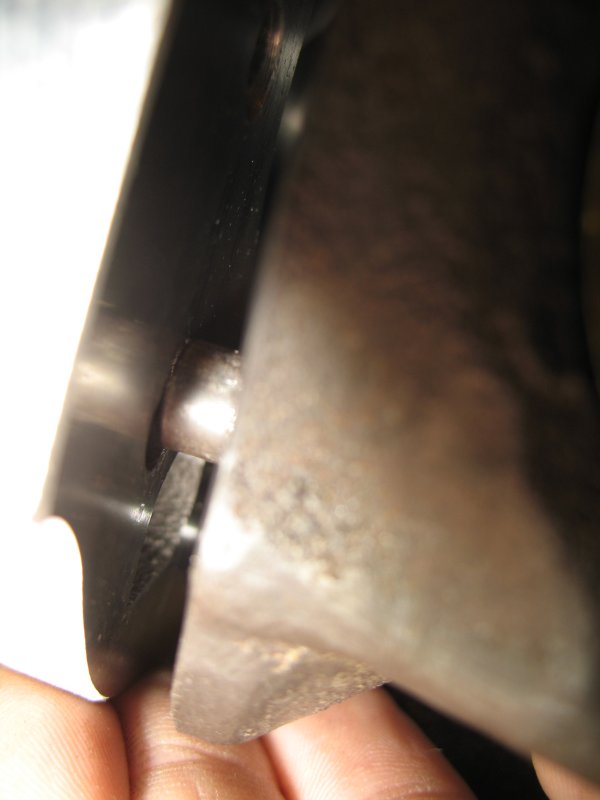
Why it pays to mock up parts: sometimes there's a problem! While Dart's quality control is top notch, sometimes problems slip through. In my case, the dowel holes in the heads were positioned incorrectly. I contacted Dart customer service, and they replaced the head with a new one. They stand behind their product!
It's finally time to assemble the heads...
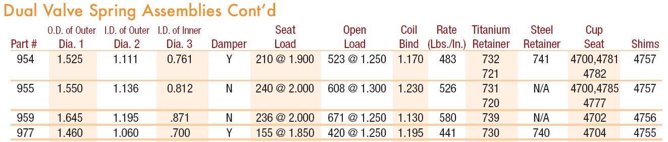
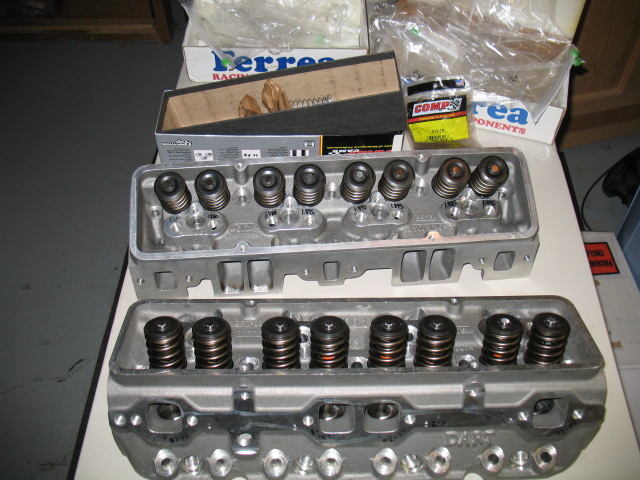
I am using Dart Pro 1 23* heads with 64cc combustion chambers, 215cc runners, and angle plugs. Since these are aluminum heads, a spring seat is required so that the springs do not dig into the heads. I am going to be running a Comp Cams XR274 solid roller cam. The manufacturer recommends their Comp Cams977 springs for that cam, and the y recommend their Comp Cams 740 retainers. It is important to verify that the retainers fit correctly on the springs. They should fit snugly, but without binding on the spring.
Everything needs to be numbered so the same parts are used on final assembly as during mockup to ensure the measurements and fit are consistent. The heads are interchangeable side to side, but for convenience a left and right should be picked, and they should be labelled with the cylinder numbers. The valves themselves should also be labelled with the cylinder number. This is especially important for good valve sealing if machining is necessary for proper fit.
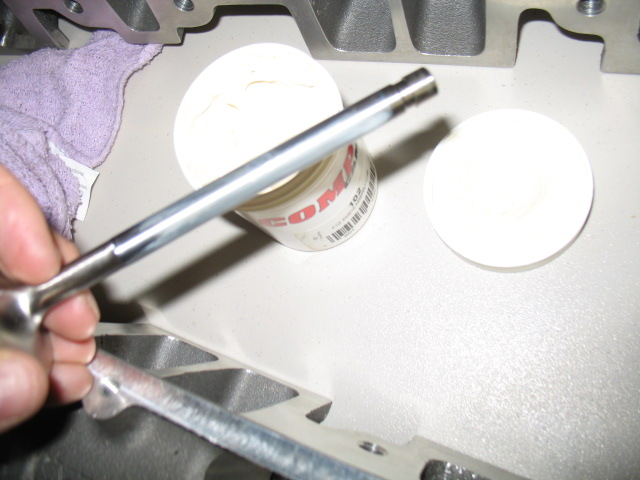
Before you start the assembly, it's important to check for a good seal between the valve and the seat. I did this by putting dry-erase whiteboard marker on the valve seat and the margin on the valves, putting in a valve, and rotating it very slightly. Take the valve back out, and the marker will be smudged off where there is contact. In my case, there was not a good contact pattern. I took the heads and valves to a machine shop and had them touched up. The valves sealed very nicely after that, and have a good contact pattern.
Before doing anything, the deck surface of the heads should be checked for straightness. This can be done using a straightedge and feeler gauges. Lay the straightedge across the head at different locations, and in different directions (straight across long direction, diagonal) and see if you can fit a feeler gauge between the straightedge and the head surface. In general, variations of less than .005 are acceptable.
The clearance between the valve stem and the valve guide should be verified as well. This can be difficult to measure, as it requires a hole gauge, or a very small bore gauge. The stem and guide should be measured at the top, middle, and bottom of their length. Check with the manufacturer's specs for the proper clearance values. Again, follow the labelling, and make sure you're measuring the valve and the specific guide it will be used in.
Another thing that should be done is to check the valve spring pressure at the installed and peak lift heights. These figures should be compared with the specs from the spring manufacturer, as well as the specs for the cam you are using.
In my case, the guide clearance and deck straightness were verified at the machine shop when they touched up the heads for proper valve sealing.
Coil bind is the height of a compressed spring when the coils begin to touch. Coil bind is a bad thing, and can lead to valvetrain component failure. The manufacturer of the springs will spec the coil bind height, but it is a good idea to verify this when you are checking the spring pressure. Using a spring pressure tester, the pressure will increase gradually as the spring is compressed. At some point, the pressure will start to increase at a higher rate because parts of the springs are starting to touch. The point at which the pressure starts to increase at the higher rate is the coil bind height. Make sure that the coil bind height is not greater than the manufacturer's specifications. The safe minimum spring height is somewhat less than the bind height. Typically you do not want to run a cam and rocker arm combination that will produce lift closer than .080" to coil bind height. If you change cams, or change rocker arm ratios, you should verify that you have proper clearance.
Another thing that can limit the maximum lift is the distance between the spring retainer and the valve seal. Again, this should be measured and verified before final assembly.
The installed height of the spring is the height of the spring when the valve is closed. It is the distance between the retainer and the spring seat. There are many things that can affect this measurement, including slight variations between parts, the machining of the valve and seat, as well as the machining of the spring pocket.
In order to get the springs to provide the same pressure on each valve, the heights must be set to the manufacturer's specification. If the height is too tall, the spring pressure will be too low. If the height is too short, the spring pressure will be too high, and the amount of travel before coil bind will be reduced. The spring heights are adjusted by using shims to achieve the right height.
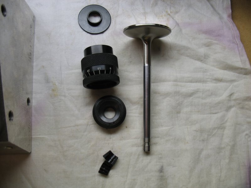
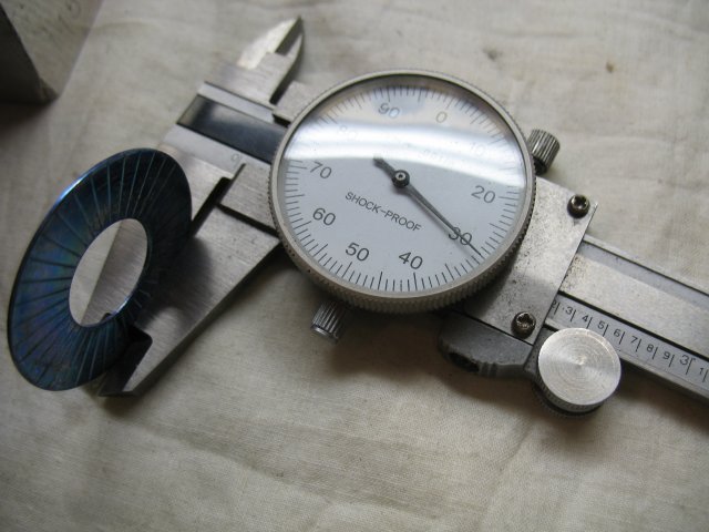
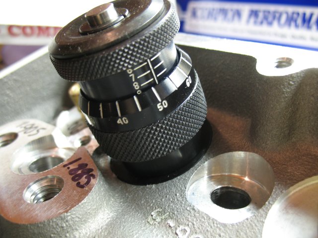
I used a spring height micrometer to measure the distance. It makes the job much easier. The one pictured is a Proform part# 66902.
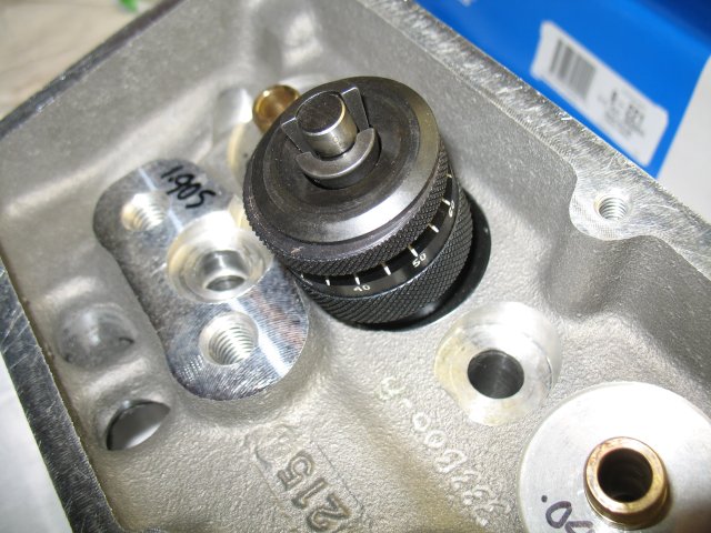
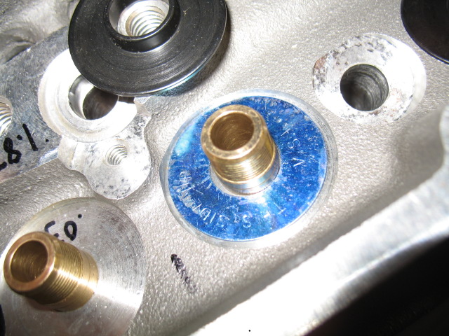
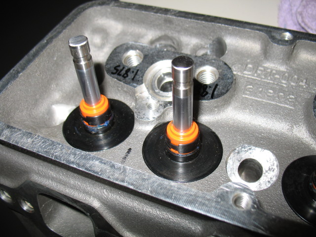
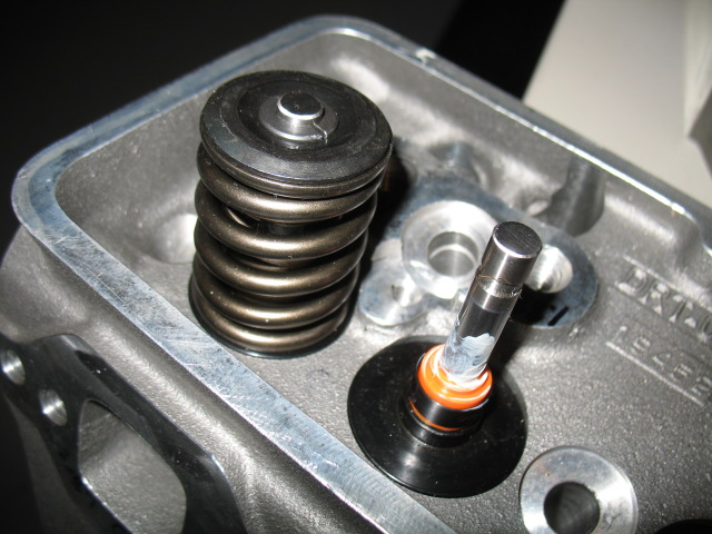
Install the valve and put on the spring seat:
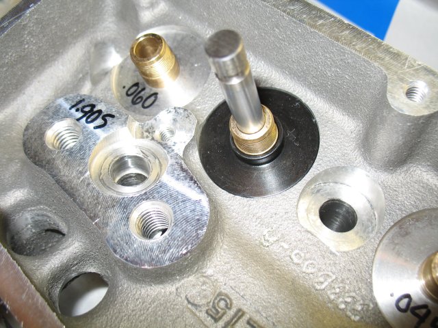
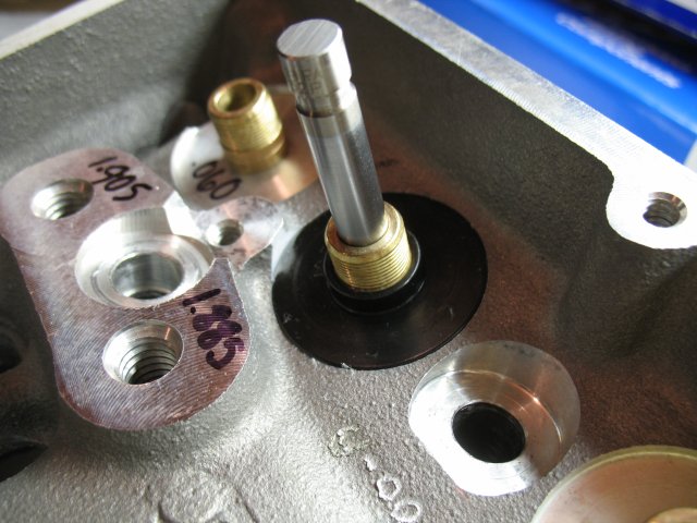
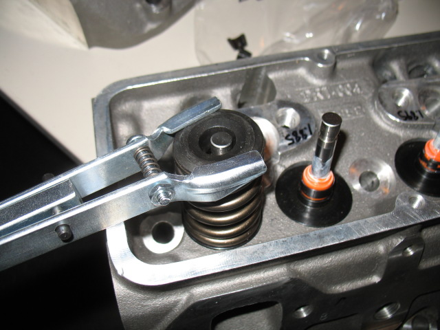
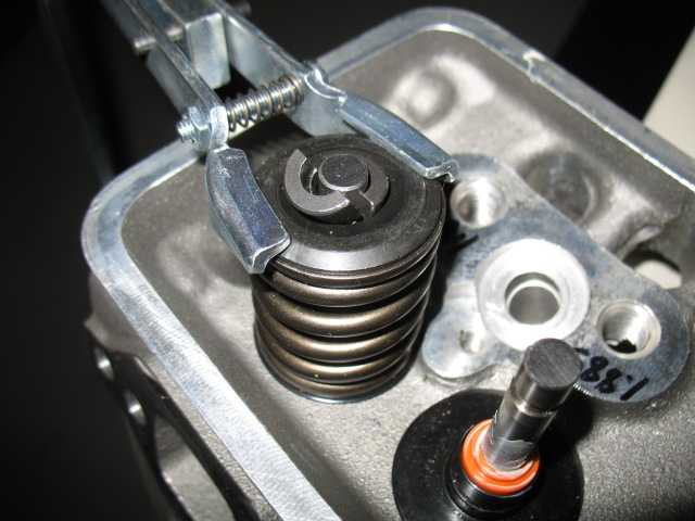
Next is the micrometer:
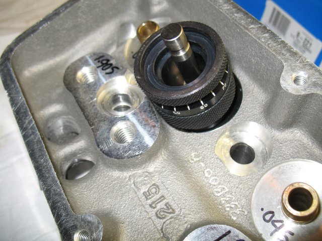
And then the spring retainer and keepers:
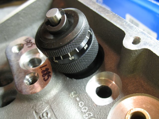
Tighten the micrometer until it stops. make sure that the keepers are fully seated in the retainer. The reading here is 1.885" The horizontal 8 stripe is completely showing, so that means we're at 1.8xx inches. The vertical is reading between 80 and 90 on the barrel, in fact it's exactly at the midpoint, or 85. That is the thousandths mesurement. 1.8 + .085 = 1.885" Note that the 9 horizontal stripe is just below the barrel of the micrometer, which means we're just under 1.9", which checks out with the 1.885 result.
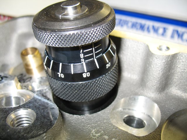
Write it down:
The Comp 977 springs require a 1.850 installed height.
The difference between the measured height and the specified height is the thickness of the shim needed. In this case, 1.885 - 1.850 = 0.035"
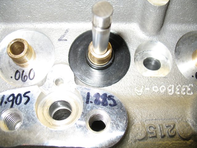
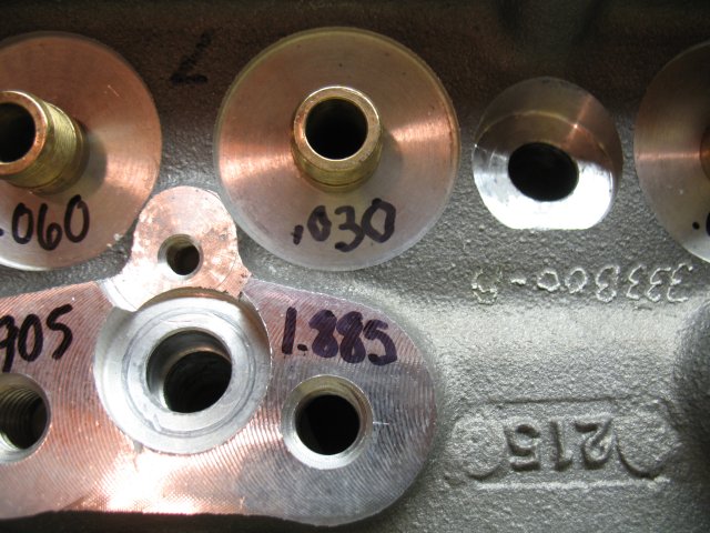
The shims come in different thicknesses, typically in .015" increments, so the choice is between 0.030 and 0.045 for this one. 0.030 is closer to what is required, so that is the right one to use:
Several shims can be stacked to get to the correct height if needed. Once the correct shim amount is selected, everything should be assembled again so the height should be verified. The shim should go under the spring seat so the spring does not dig into the shims. Note that the shim has a top and bottom. The serrations should face down towards the head so the 'THIS SIDE UP' shows
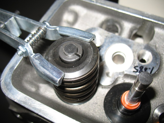
Next, install the spring seat on top of the shim:
Finally, put on the micrometer, retainer, and keepers:
Tighten the micrometer and check the reading. With the shim installed, the height now reads 1.852, which is very close to the spec:
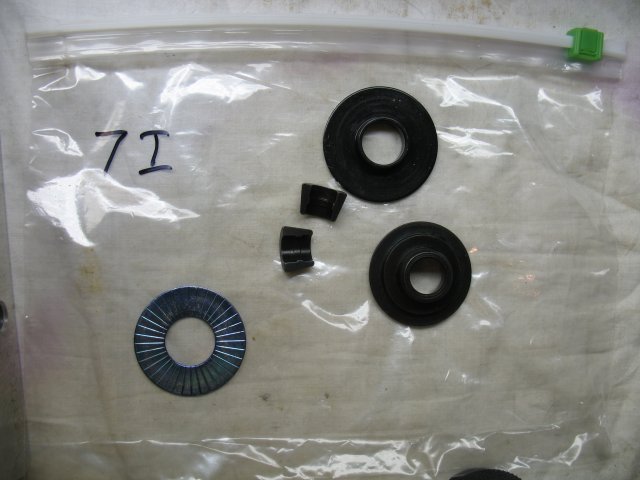
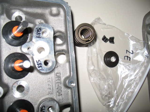
The final step is to label everything. As there are slight differences in all these parts, it's important to keep together the exact parts used during measuring. This was the intake valve on #7, so all the parts go in a bag with that label:
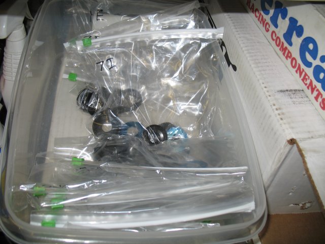
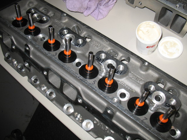
After you do this 16 times, you end up with this:
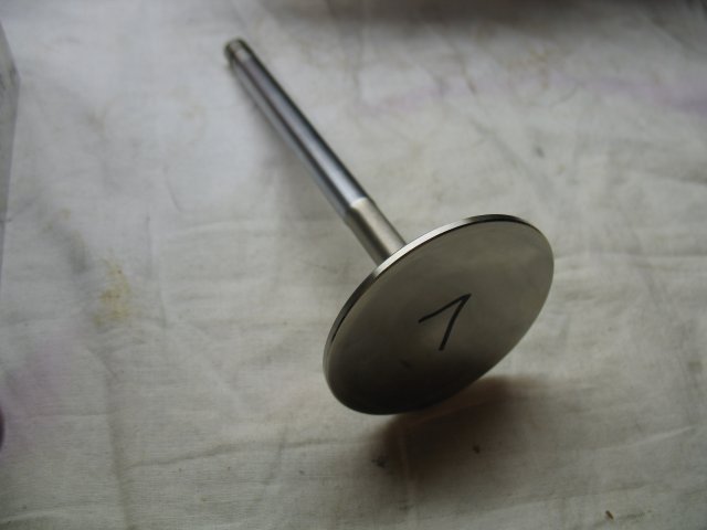
The valves should be labled as well:
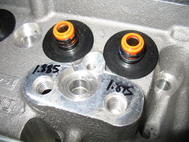
And the spring pocket gets labeled with the correct shim height for that spot:
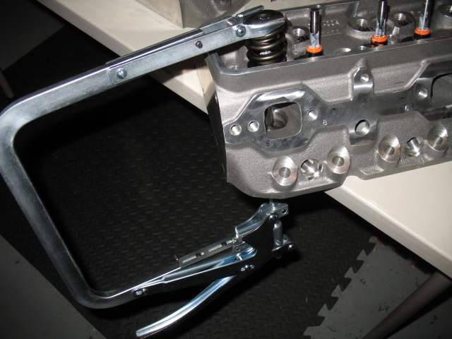
And now...on to final assembly...more text later, here's pictures:
All of the shims and spring seats get placed in the correct spots. Then it's time to install the valve seals. The seals that I used need to be glued on to the valve guides.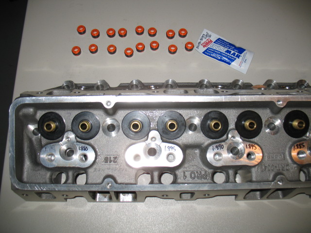
Note: all text and images on this page are Copyright 2008 by Pat Mancuso. All rights reserved.