3/31/2006 NEWS FLASH!!! This part is now being repro'ed. You can now purchase it from Chevy 2 Only:
Part Number 93056, ELECTRICAL SHUNT FOR SS AMP GAUGE
-----------------------------
I finally got my hands on a mythical NOS ammeter shunt. This is used on the 1963-1965 Nova SS, as well as the 1963-1964 Chevelle SS.
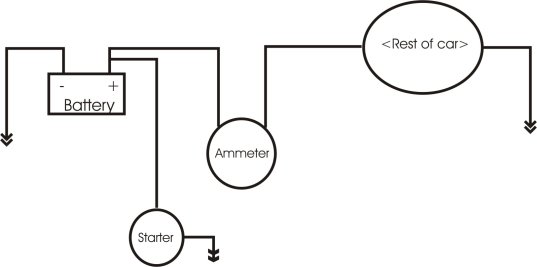
Other ammeters run all of the current through the gauge. If you hook up the stock gauge in this manner, you will cook the gauge. Don't do it...:
This one works a bit differently. It looks for the current drop across a resistor (shunt) and uses that instead of a direct current measurement:

Here is the original SS wiring diagram:
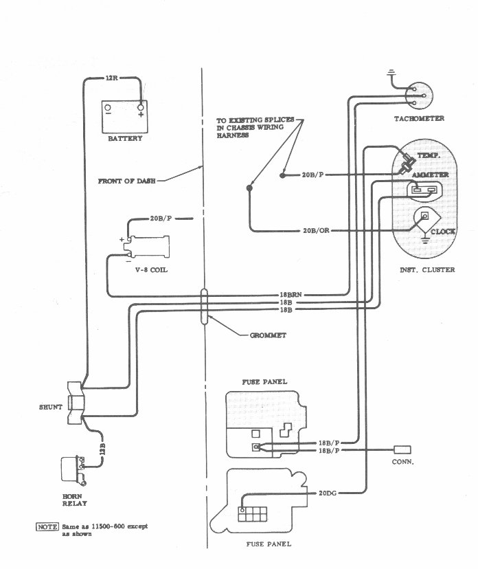
The main power goes from the battery to one side of the shunt via a 12 gauge red wire, and then from the other side of the shunt to the horn relay via a 12 gauge black wire. Everything on the car (except for the starter) is supplied power via the lug on the horn relay. The diagram shows that the ammeter is connected to the lugs on the shunt by two 18 gauge black wires. This is the factory setup.
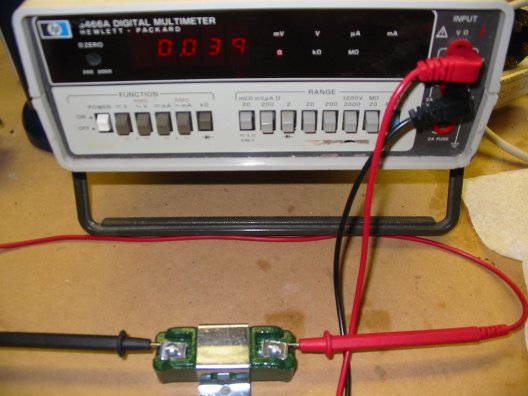
The shunt is Delco part number 1961149, Here is what it looks like:
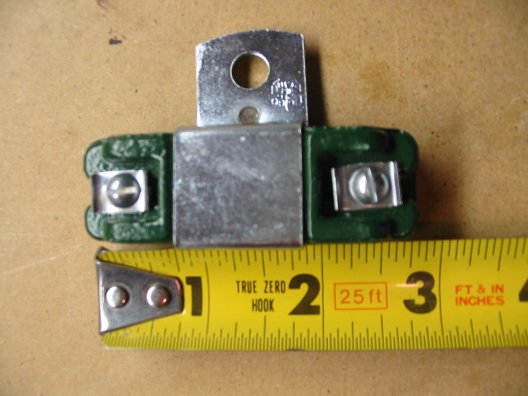
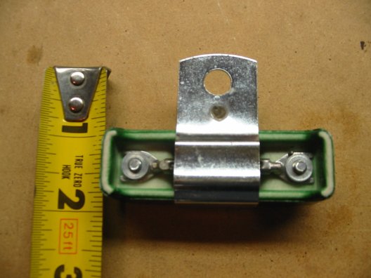
Although it looks something like an ignition ballast resistor, it is not. It is a very very low value resistor, I measured it at 0.039 ohms (not Kilo-ohms, just plain ohms) By comparison, an ignition ballast resistor is about 0.9 ohms.
These shunts are getting very difficult to find, and are expensive when you can find them. There is another way to get the ammeter to work however, it involves making a low ohm resistor that can handle the current...out of 18 ga wire.
How it works:
Pretend you have a 2" water pipe that is the main water feed for your house. You want to measure the flow. You have a flow gauge that you want to hook up.
1) you cut out a section of the pipe and put the flow gauge in place of the removed section. All the flow goes through the gauge. Works great, but all of the flow has to go through the gauge, and the gauge is pegged.
2) you drill two 1/4" holes in the pipe, 8" apart. You hook up 1/4" tubing to the two holes, and connect those to the gauge. Now most of the flow is going through the big pipe, and little or no water is going through the smaller pipe. The gauge is no longer a critical item to keep up the flow, but you're not reading much on the gauge.
3) same deal, but you cut out 6" of the pipe in between the two holes and put a 1" diameter pipe in place. Now there is a restriction in the main pipe, so more water will flow through the small tubing. You get more flow through the gauge, so you get more of a reading on the gauge.
4) think about #3, and using smaller and smaller sizes of restrictor pipes. The smaller the pipe, the more flow is forced through the gauge. If the restrictor pipe is so small that it completely cuts off the flow, you're back to #1.
The shunt is the restrictor pipe. The amount of resistance controls how much juice flows to the ammeter gauge. No shunt, gauge spliced into the main power line, huge amount of juice to the gauge, it pegs and fries. low resistance shunt, just the right amount of juice to the gauge. Too low resistance, very little juice to the gauge, the needle doesn't move much.
Replacement for shunt:
The workaround is to use the natural resistance of wire as a shunt. The 5' of 12 ga wire that goes from the battery across the radiator support to the horn relay is a good candidate. That provides a little resistance, so if you hook up one side of the ammeter to the battery, and the other side to the horn relay, the 12 ga wire across the radiator support is acting as a mini-shunt. From what we've calculated in previous posts, the resistance of the wire is a bit low to get enough 'oomph' diverted to the gauge, but it should be enough to see some reading on the gauge.
More on the measurements:
I triple checked the measurements with my meter (let it warm up for a while, made sure there were good connections, etc.) and again got .039 ohms.
I happened to have a coil of 12 ga romex laying around, and I measured .110 ohms on it. It turned out to be about 46' when I measured it.
Now I'm not sure if there is a difference in ohms/foot for 12 ga solid vs stranded wire, but... My meter reading still comes out a bit on the high side compared with what the math works out to: 46' x .0018 ohms/foot = .0828 ohms. Assuming the ohms/foot is correct for the solid wire, I'm off by .0272 ohms, or 25%.
So...given that error, the range of values I'd put on the shunt would be either .039 +/- .0272 (.0118 to ..0662), or .039 +/- 25% (.0293 to .0487) depending on if you believe the error is a fixed amount or a percentage.
Personally, I'd believe that it's a fixed amount, probably due to surface (dirt) resistance between the probe and the wire or shunt instead of a percentage. Assuming that, the 'real' value could be .0118 for the shunt, that is 130% of the .009 value that you'd get from a 5' length of 12 ga wire. That would mean you'd get about 77% of the needle movement from the workaround vs using the right shunt. (Looking at the other extreme, if the shunt was really .0662, that would be 735% of the .009 value, or 14% of the needle movement.)
In any case, I think the bottom line is that the battery-to-horn-relay-wire
shunt trick will work, but you'll get somewhat less needle movement than you
would with the original shunt setup.