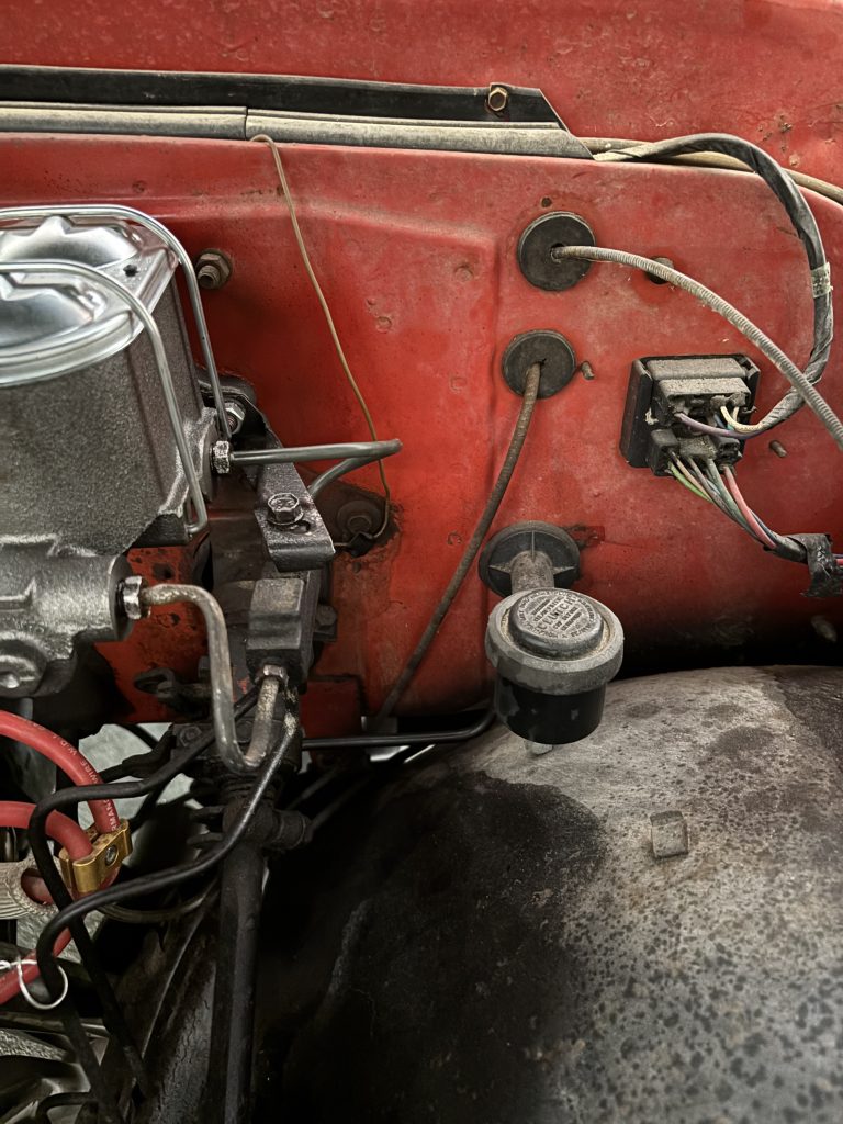
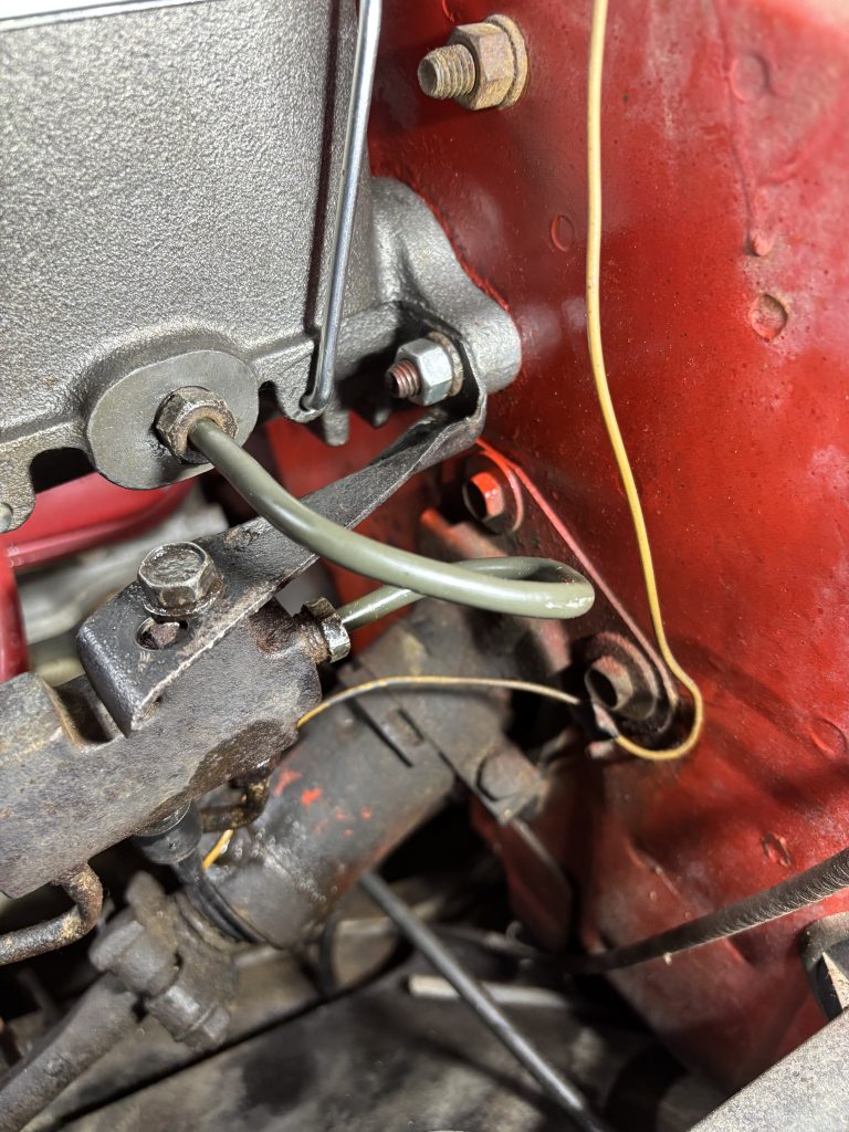
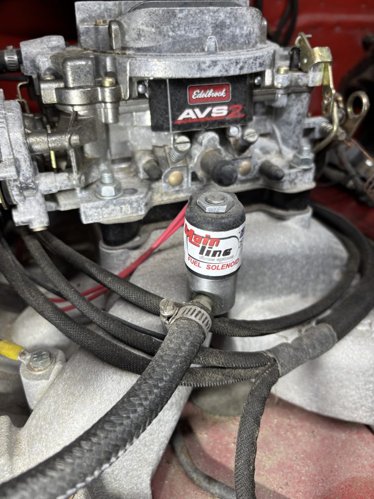
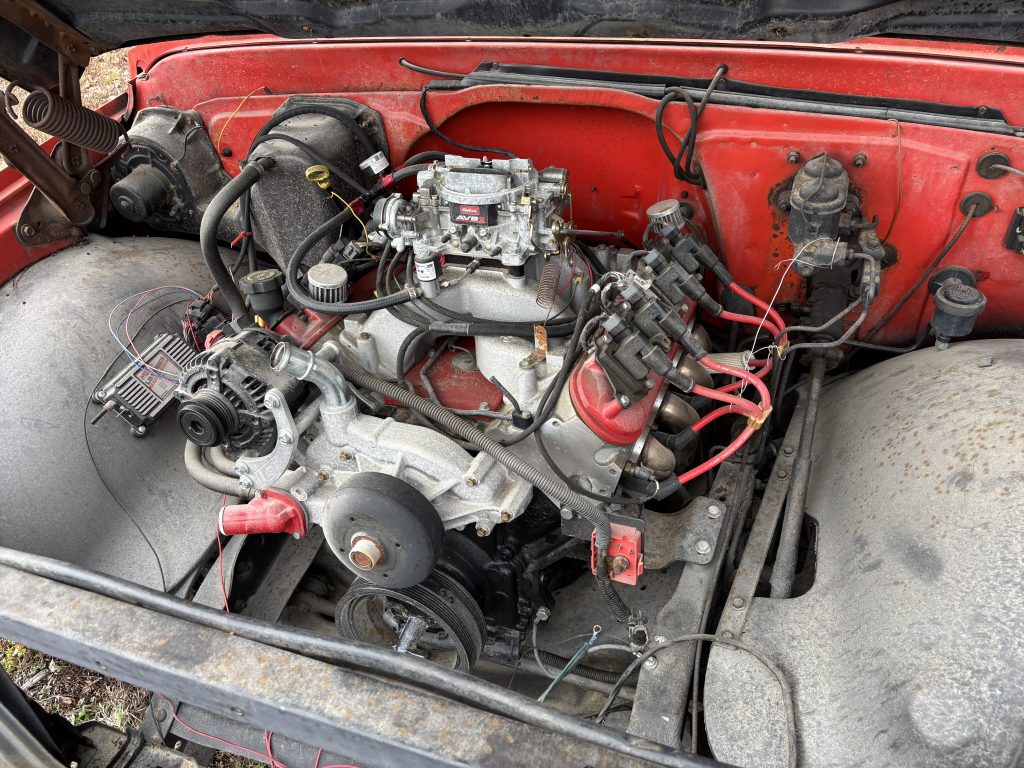
The kickdown cable is a connection between the carb and the TH350 transmission that causes the transmission to shift into a lower gear during hard acceleration. When I bought the car, the cable was not connected, and acted as though it was stuck. I assumed the sheath had melted somewhere, and that’s why it wasn’t moving. I bought a new cable, but the attachment point at the transmission was blocked by the header, so I never got around to installing it…until now.
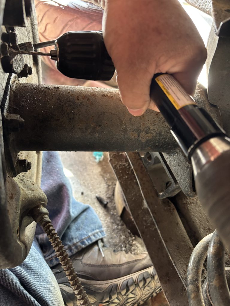
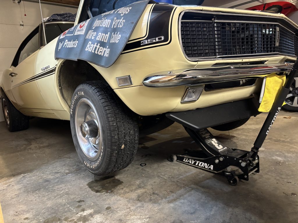
The plan was to disconnect the right-hand side header to get access to the transmission, install the new cable, and reinstall the header.
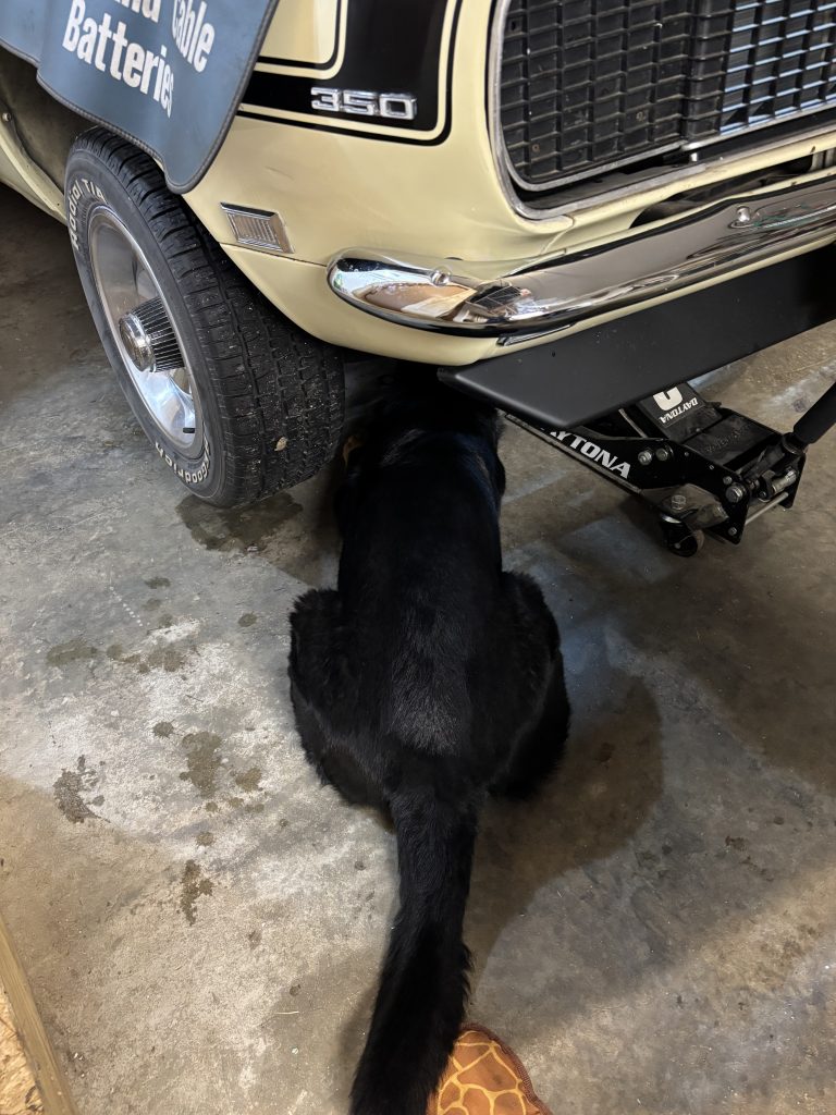
Luckily I had help.
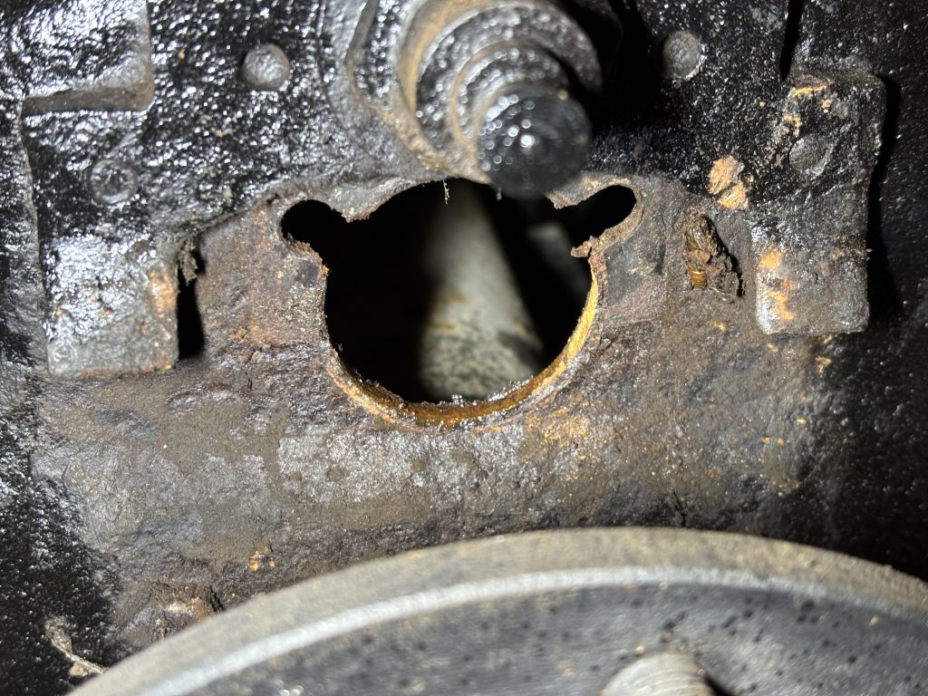
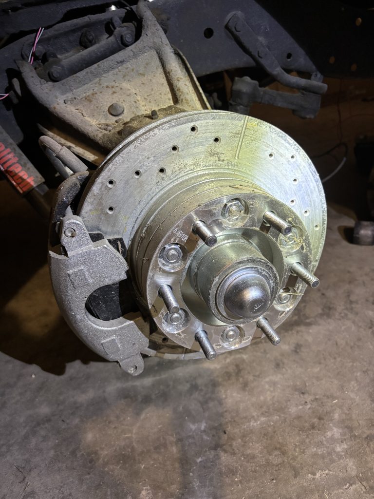
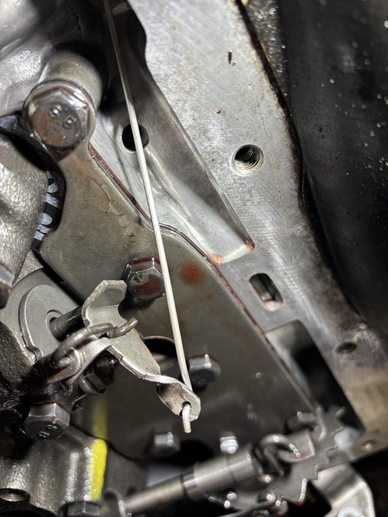
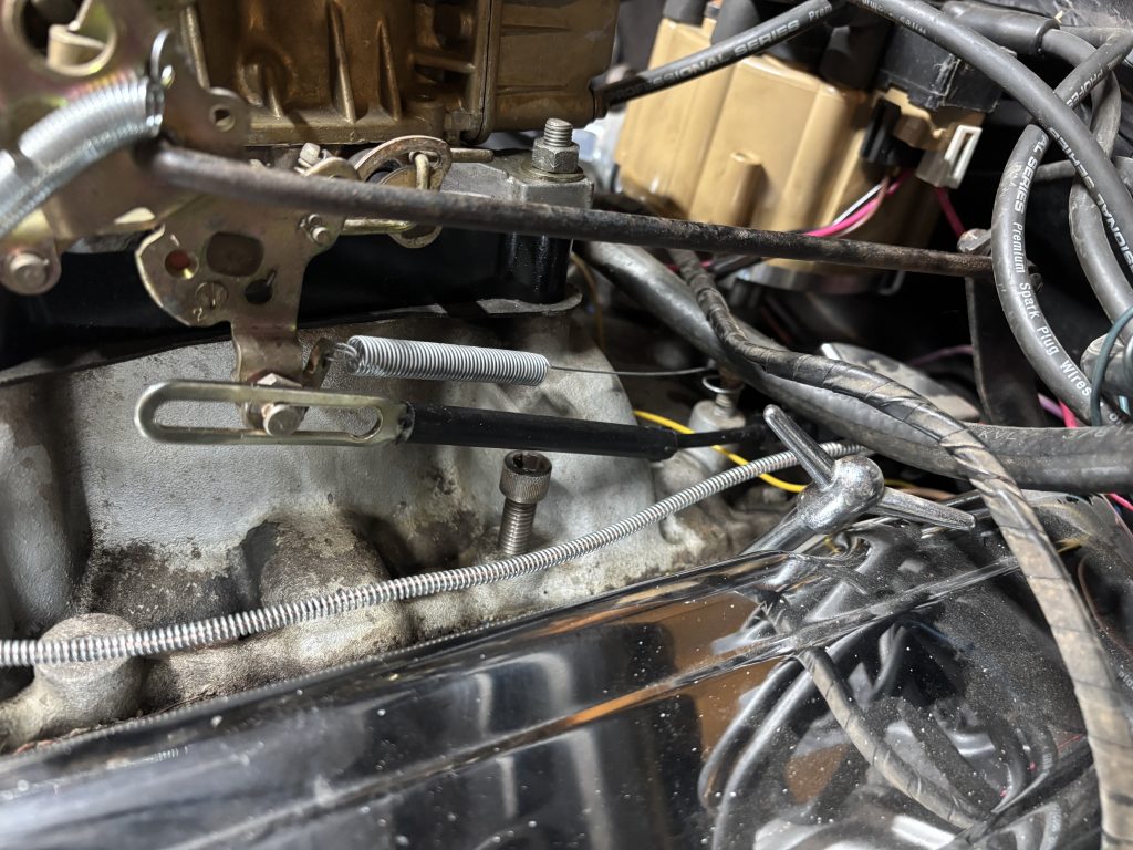
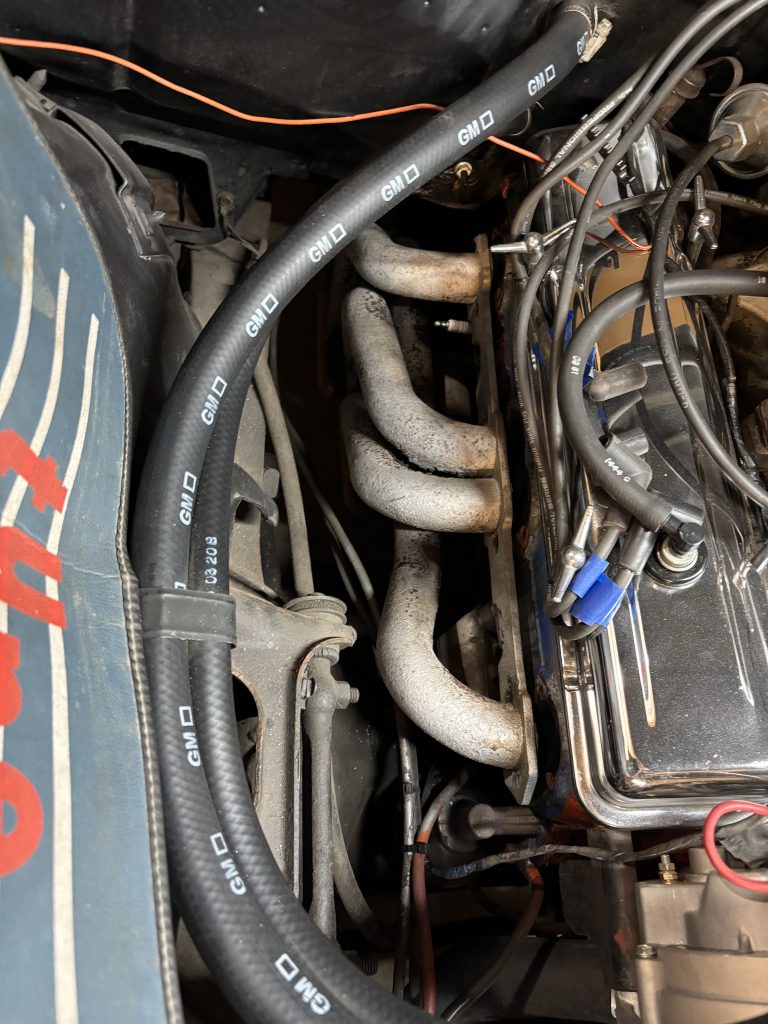
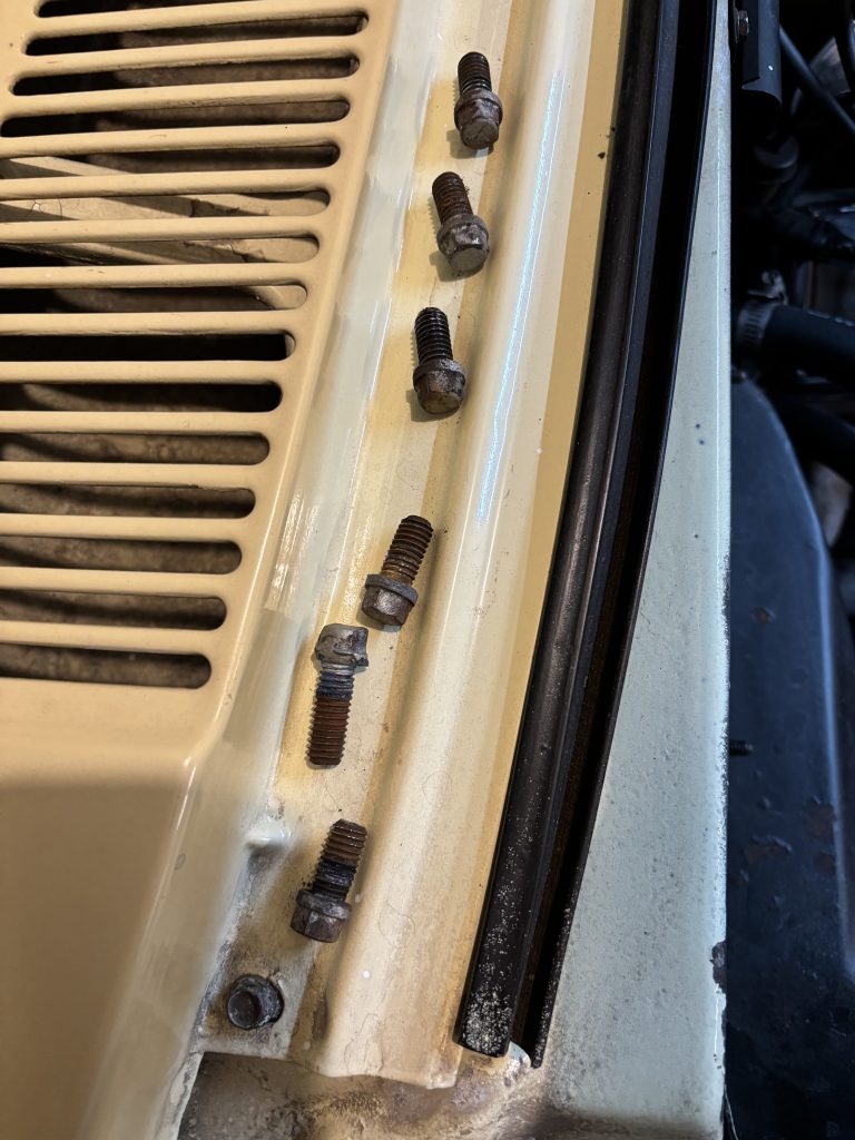
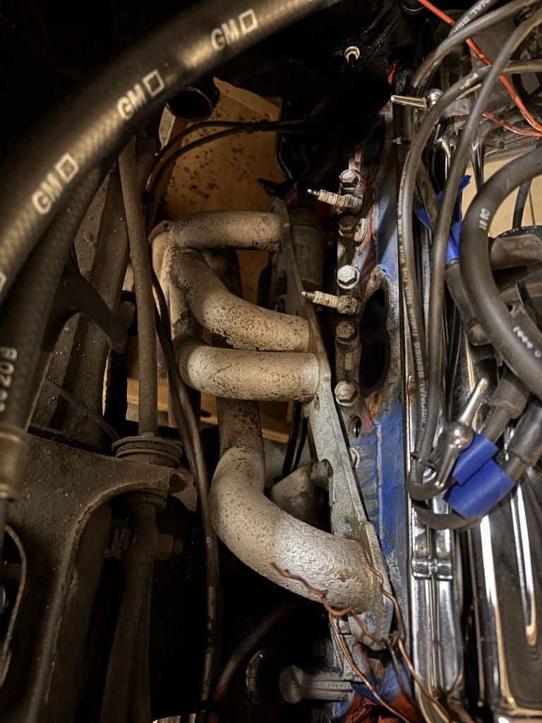
Headers are notorious for being difficult to install and remove. After an hour, I had the 6 bolts removed attaching the header to the cylinder head. Another hour had the 3 rusty bolts at the collector removed. The header dropped out of the way, and I had easy access to disconnect the old kickdown cable
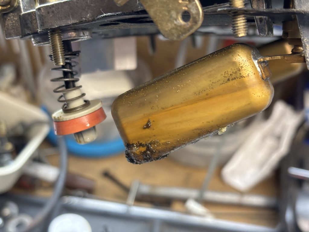
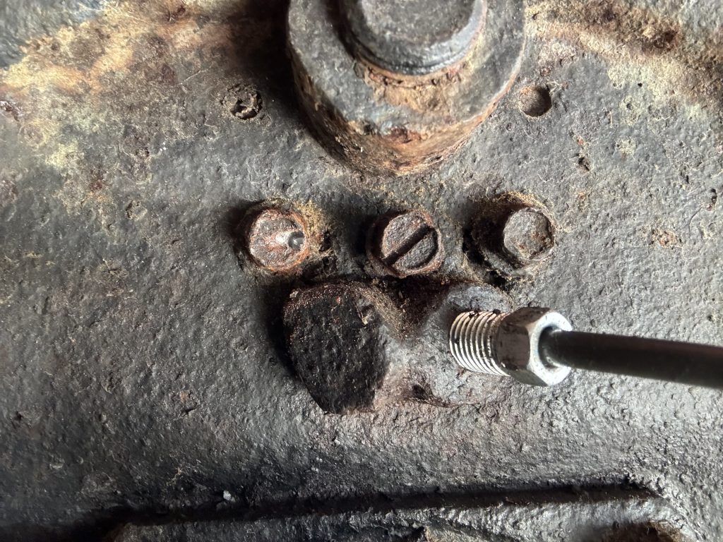
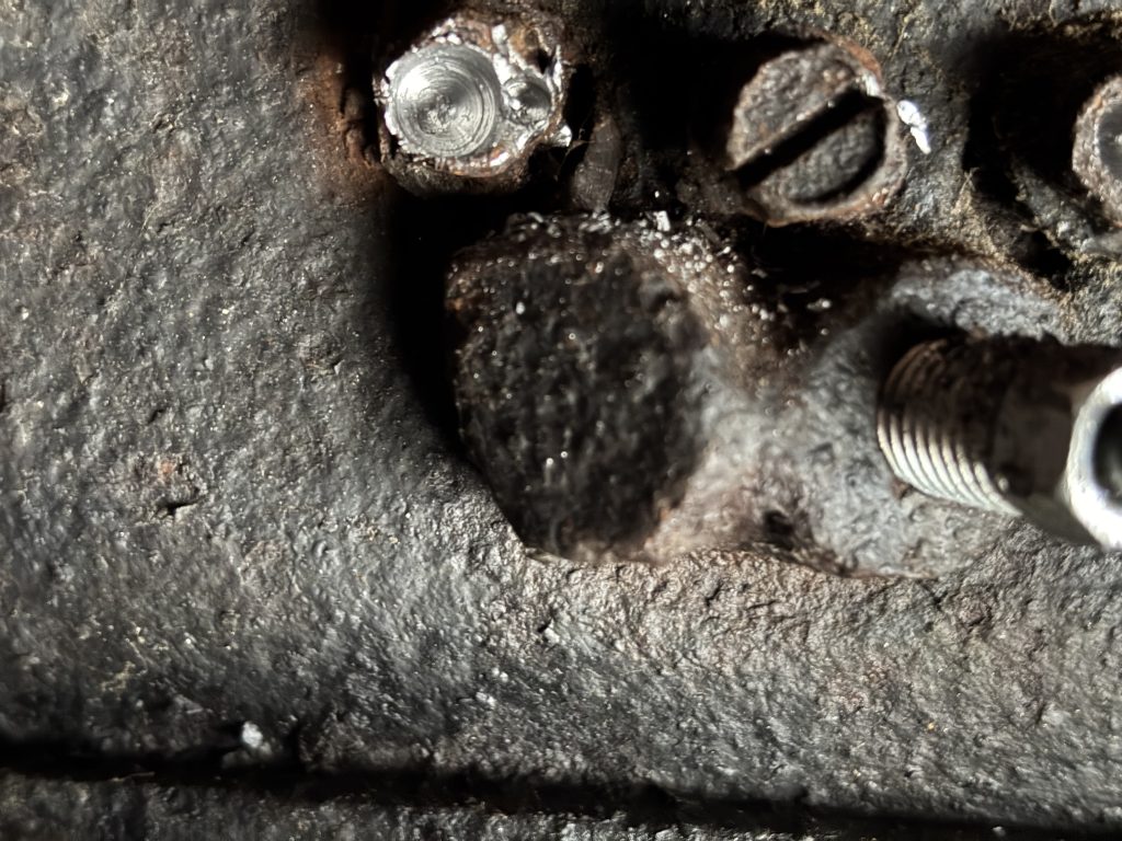
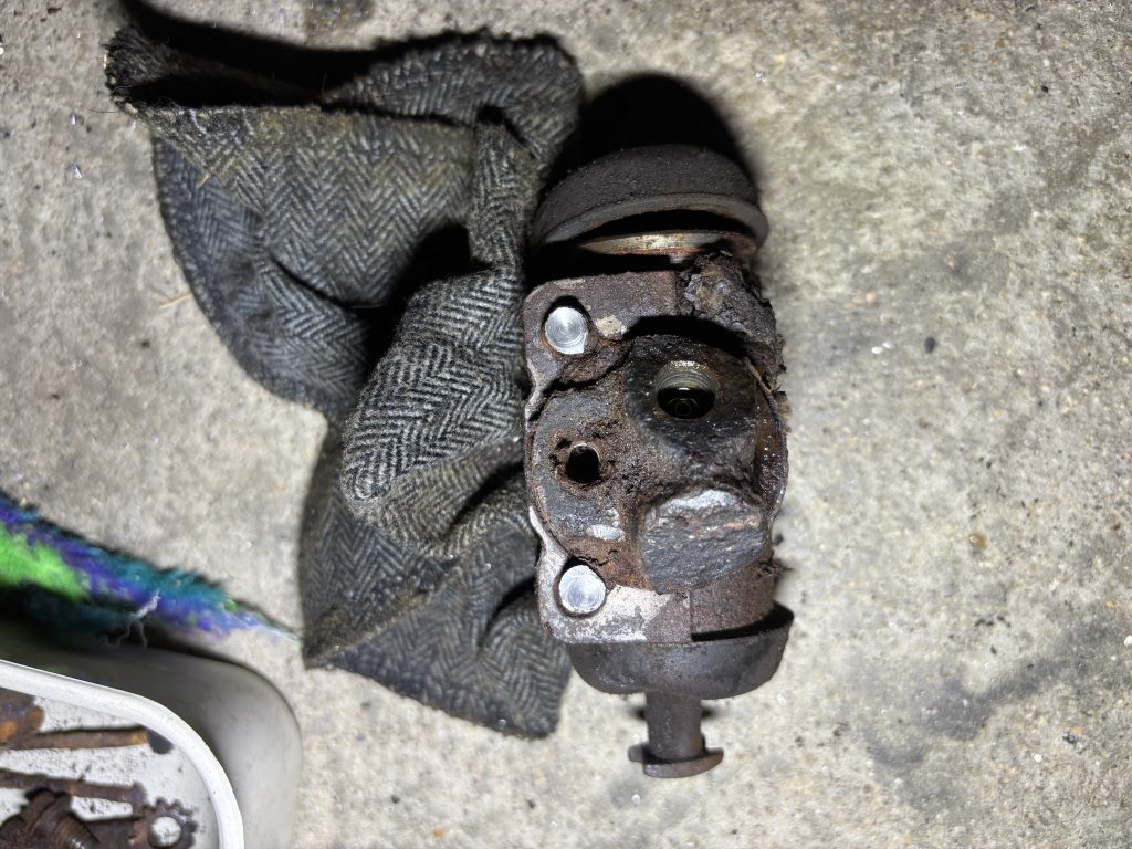
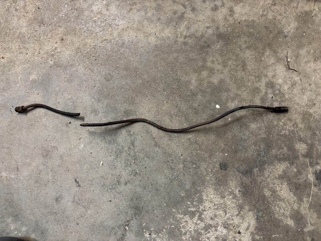
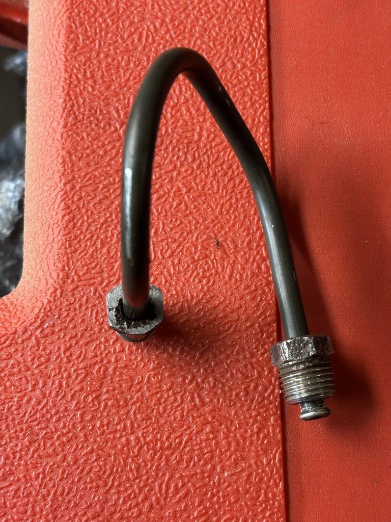
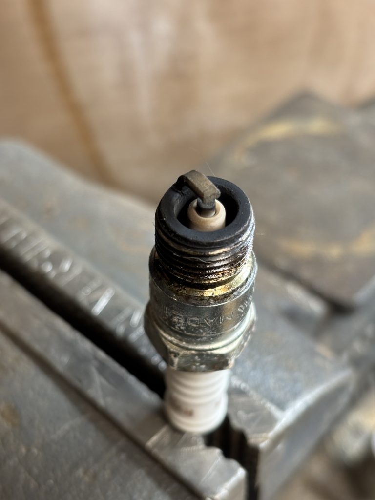
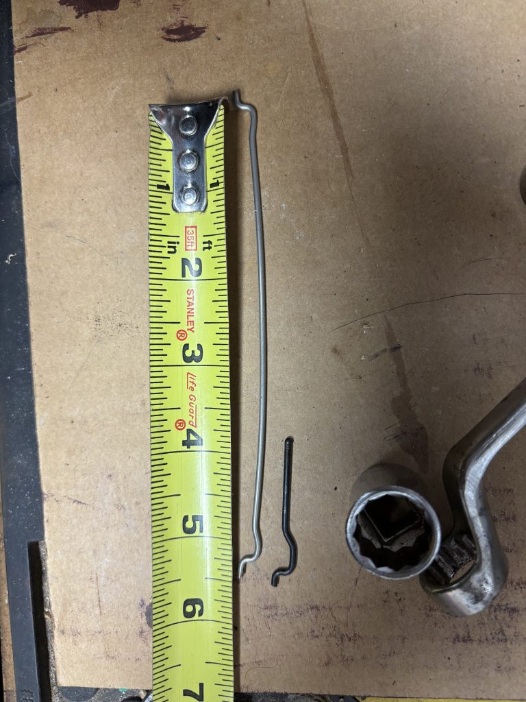
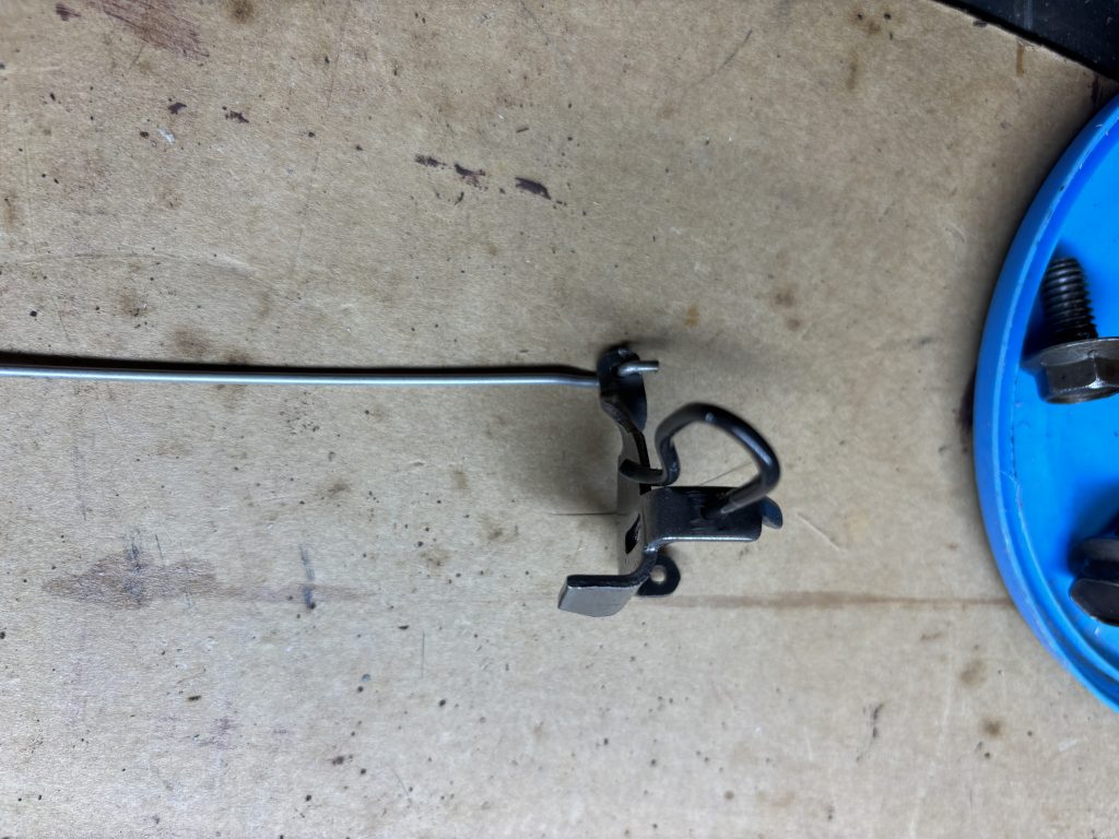
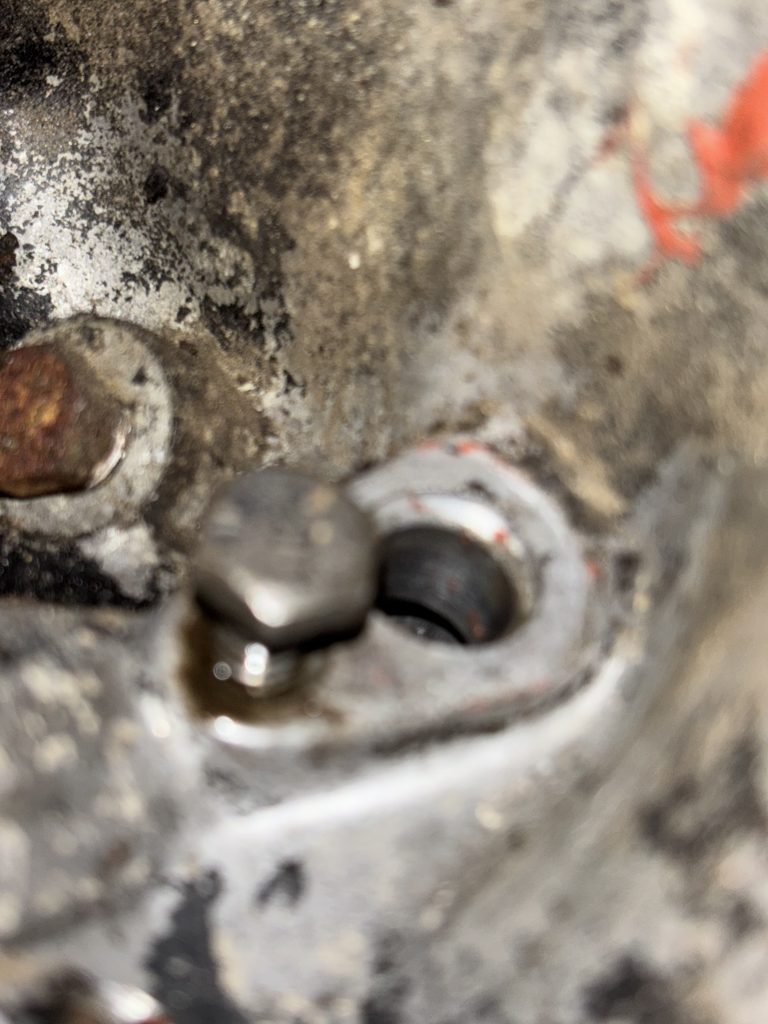
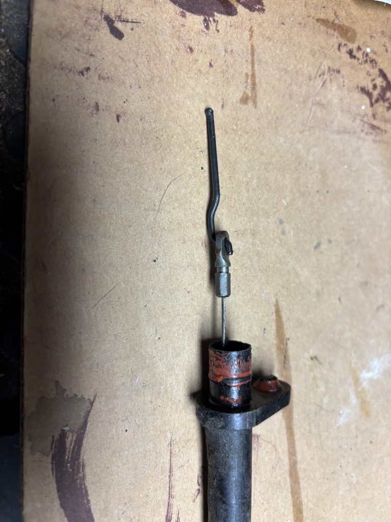
When I took the retaining bolt off and removed the cable, it came out easily, which was bad because it’s supposed to be connected to a wire rod inside the transmission. After examining the cable, I discovered that it wasn’t melted, but the cable end was wedged up in the cable sheath, along with a piece of the rod.
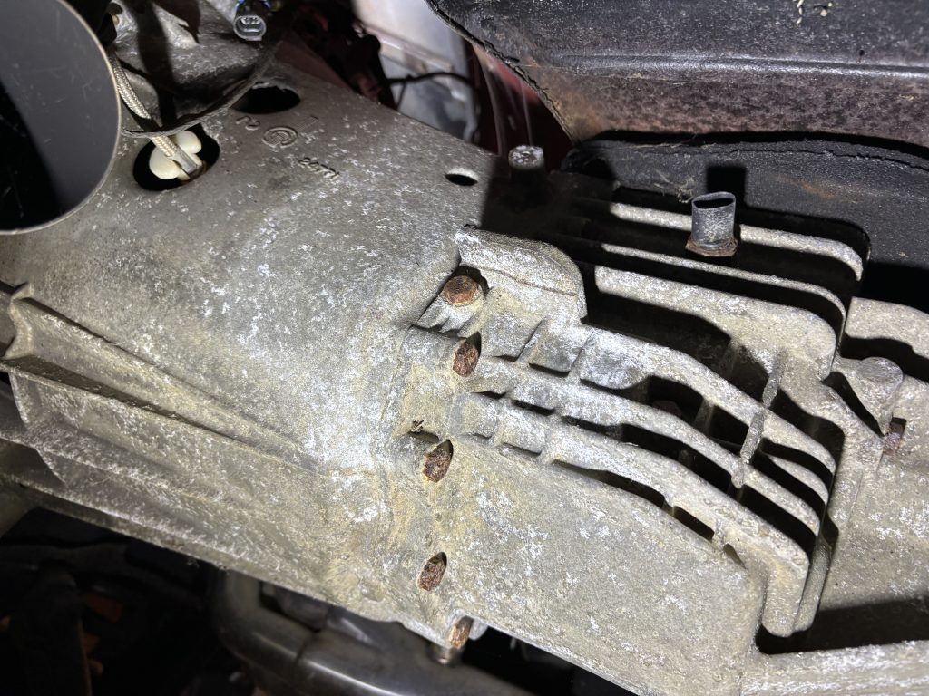
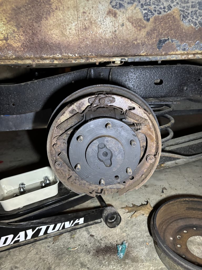
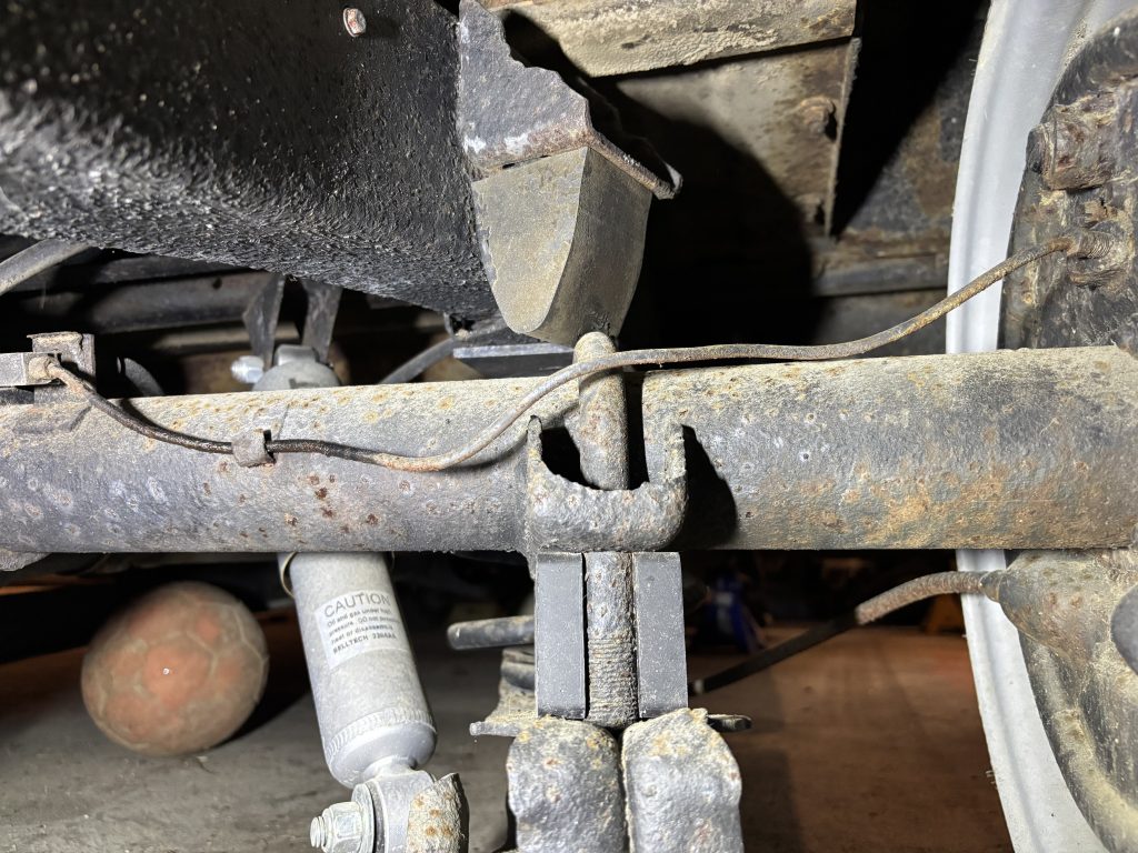
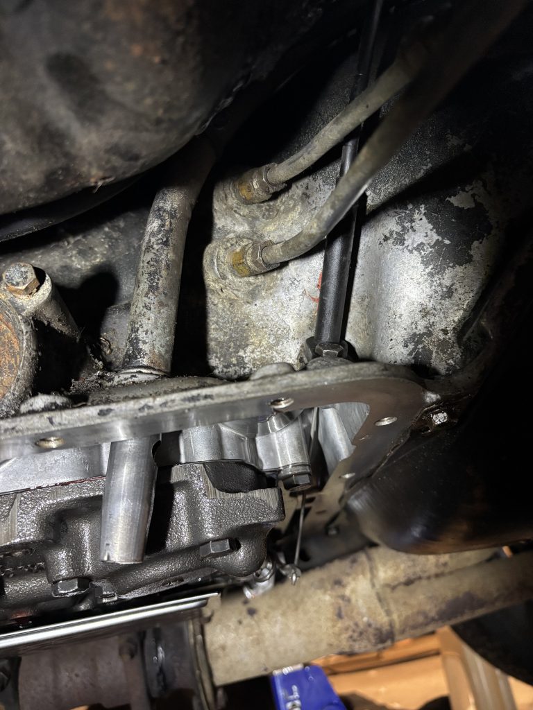
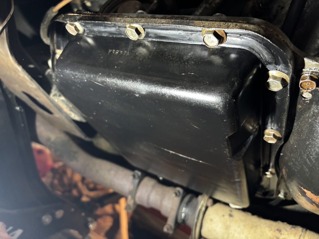
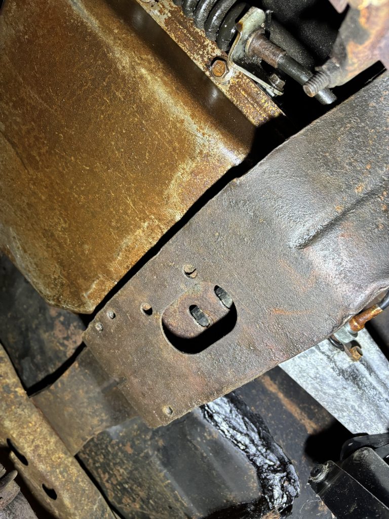
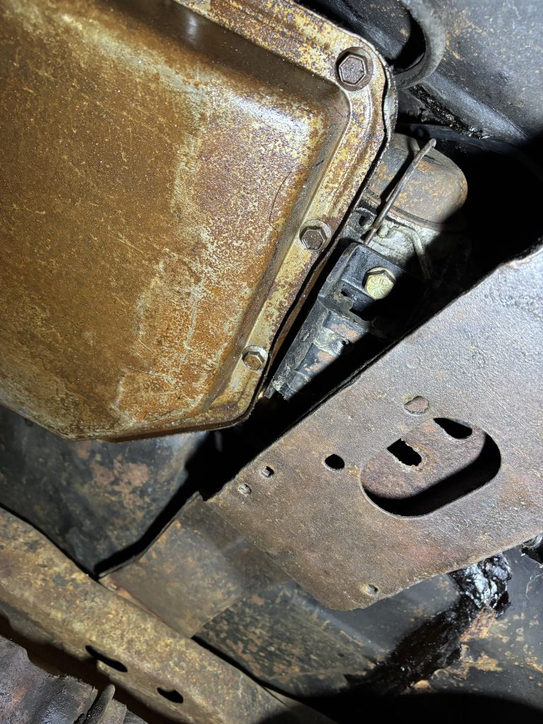
In order to replace the rod, I’d have to remove the transmission pan. The original transmission in the car was a Powerglide (2-speed), and it currently has a TH350 (3-speed). The mounting points are identical between these two transmissions, but the transmission pan extends much farther back, so the rearmost pan bolts are covered up by the transmission crossmember. In order to get to those bolts, I’d have to move the crossmember out of the way.
Thankfully, the crossmember bolts and the transmission mount bolts came out easily. I jacked up the back of the transmission a little, and the crossmember slid out of the way easily.
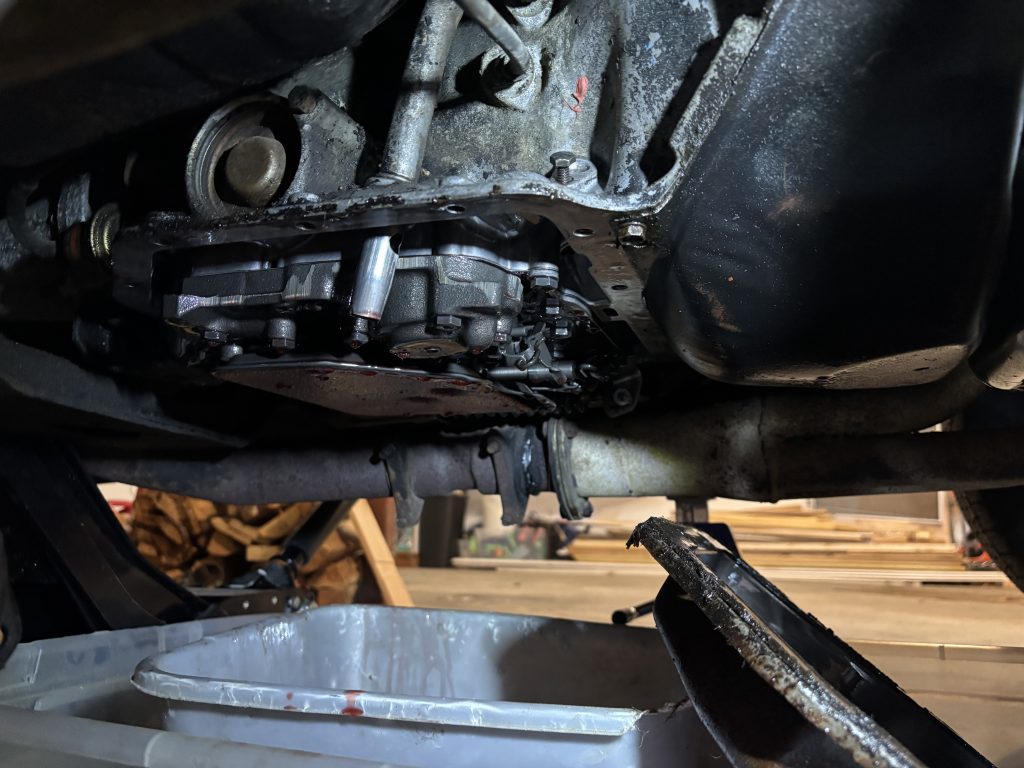
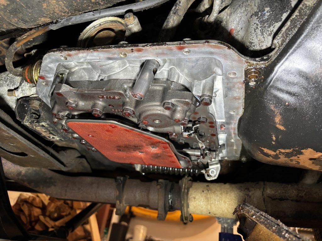
The next challenge was getting the pan off without making a huge mess. I started with one drain pan, and quickly decided I needed a bigger one to catch all the fluid. I ended up using a big under-bed storage bin, which worked reasonably well. My wife suggested one of those pans that goes under a washing machine, I think that’s a good plan.
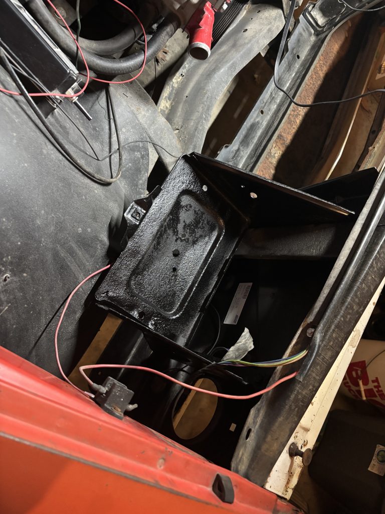
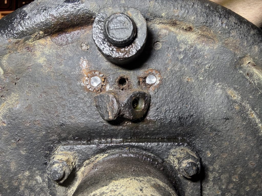
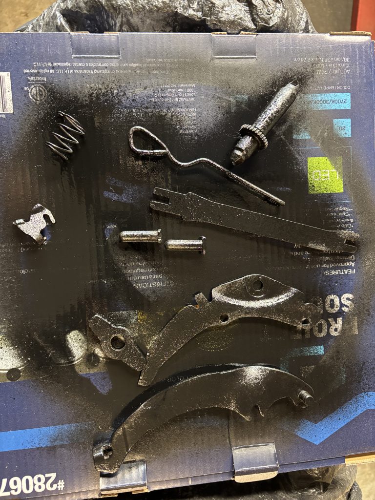
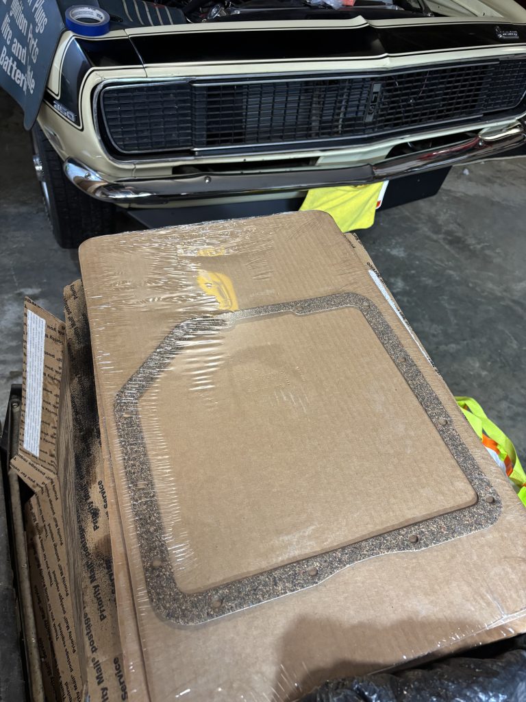
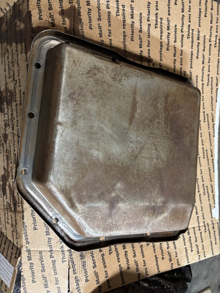
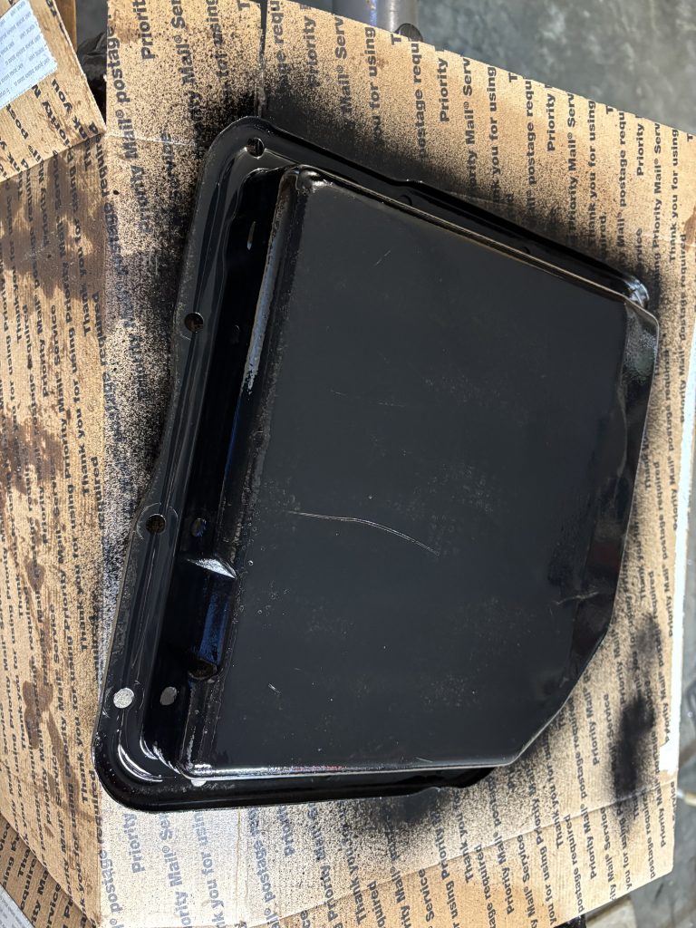
Once the pan was off, I expected to find the other half of the rod, but I haven’t found it yet. Maybe it was removed or lost previously. The inside of the pan looked reasonably clean, there was a very thin layer of dark (clutch?) material on it, but not a lot, so I’m hoping that’s normal. I cleaned and painted the pan because…that’s what you do when you’ve got a part off the car and have some spray paint.
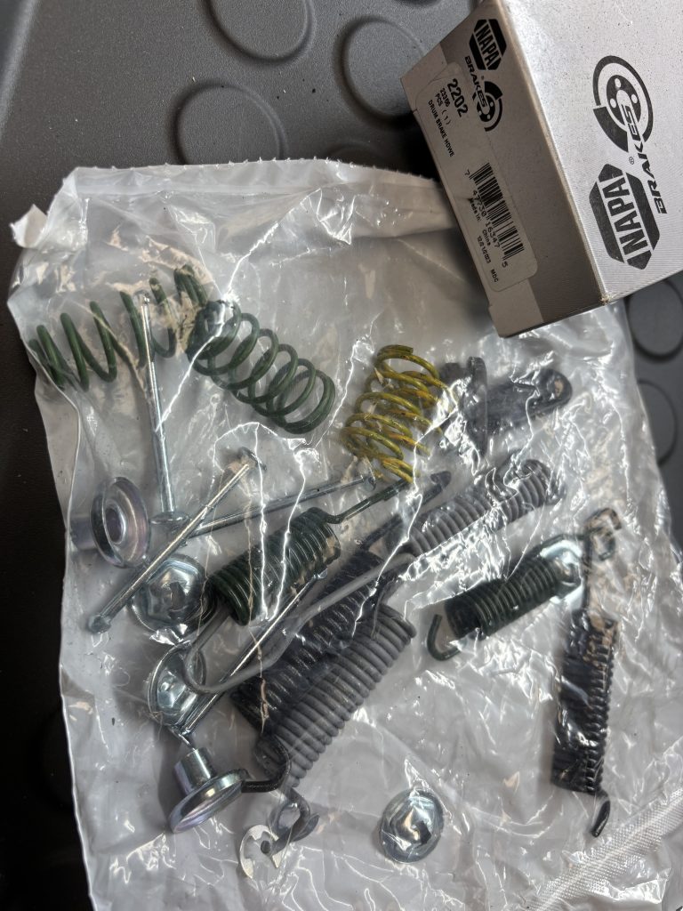
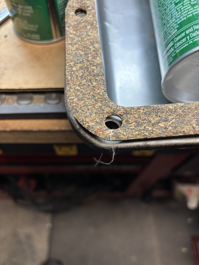
I’m going to replace the filter while I have this apart, although the old filter doesn’t look very dirty. The filter kit that I got has a rubber pan gasket but some reading shows that cork works better, so I ordered a cork one because getting to the pan bolts is a problem.
To be continued…