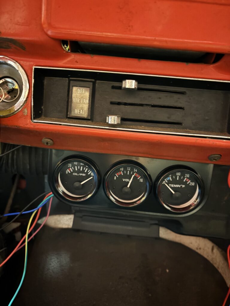
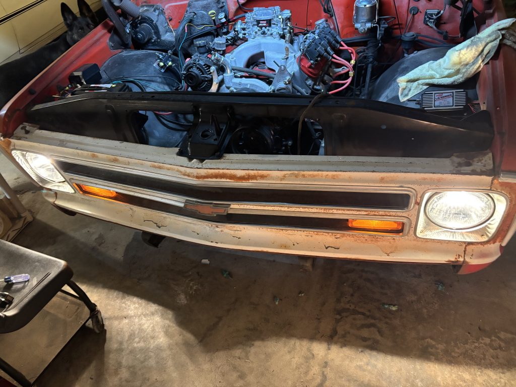
The truck is a very VERY base model. No radio, no gauges, manual choke even. I figured I should have some gauges to monitor what the engine is doing so I don’t cook it unintentionally. Longer term I may go with the upgraded instrument cluster with the factory gauges, but for now an aftermarket under-dash set will work.
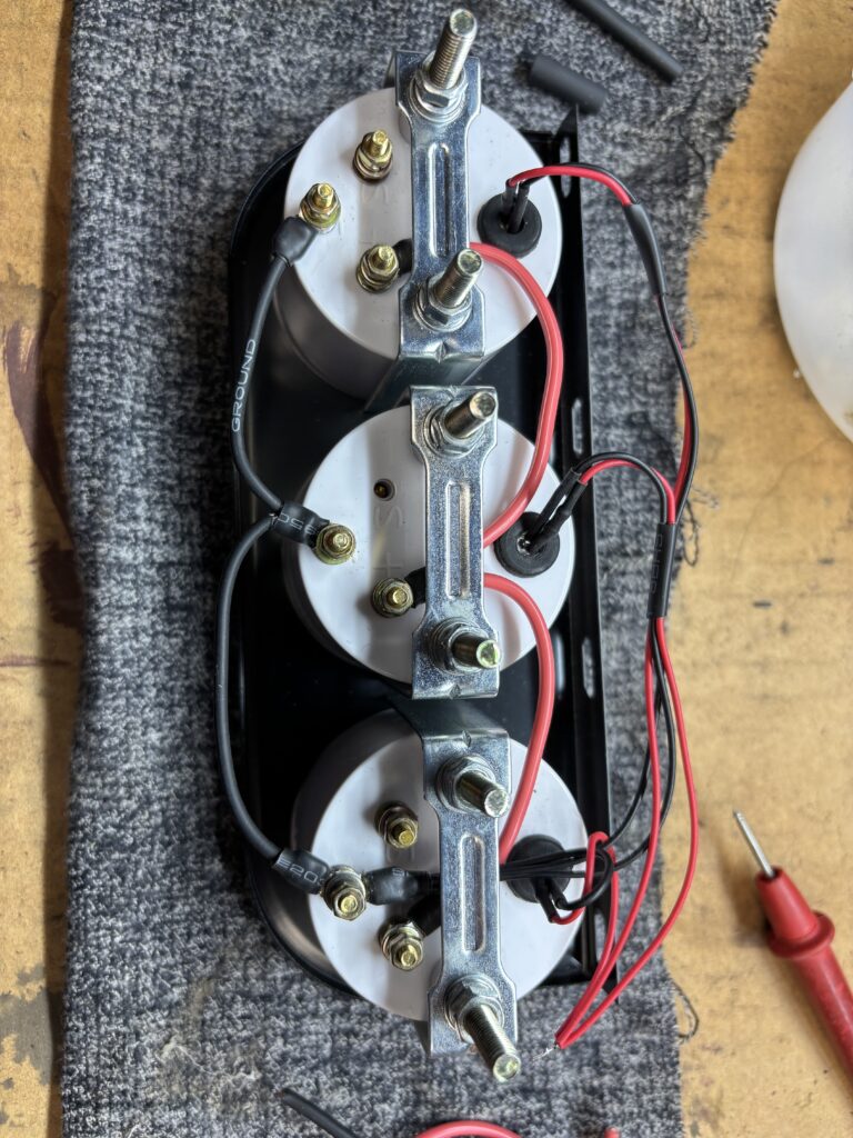
C10 under dash gauge wiring
I wired up the common power and ground connections on the back of the gauges, and also the lighting.
The volt meter worked fine, as that’s an easy connection. The LS oil pressure sender was NOT compatible with these gauges, so I’ll have to use the sender that came with this gauge set. Still not sure on the temperature sender that was on the right hand cylinder head towards the back, we’ll see what happens when I get it running.
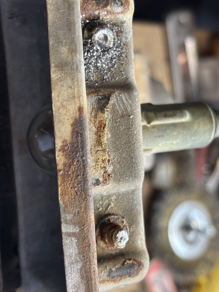
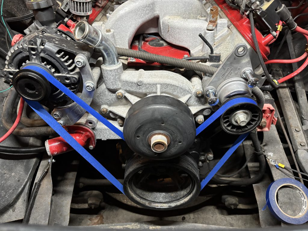
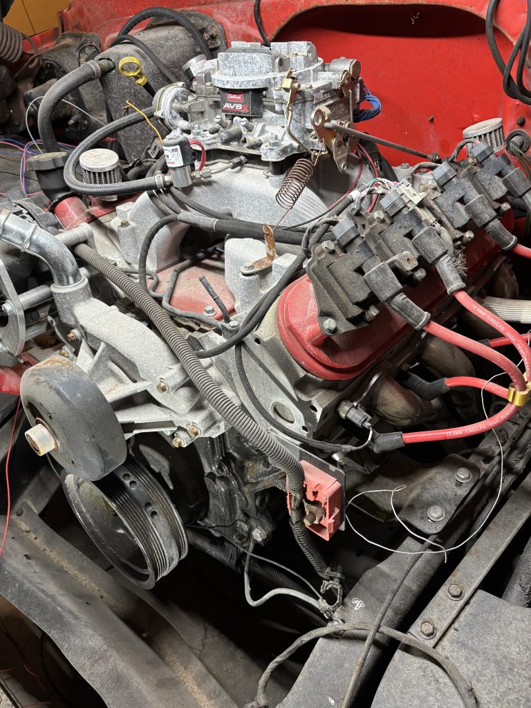
The next problem to be solved was the serpentine belt drive. This setup has no air conditioning or power steering, so the belt just needs to drive the alternator and the water pump. PO installed the alternator with an aftermarket ICT bracket, in front of the right hand head. This placement worked well, except that it took the location where the belt tensioner is in the stock configuration. I decided to move the tensioner to the left hand head in a mirror-image orientation. I could not find an aftermarket bracket that mounted the tensioner on the left, so I made my own. It’s not pretty, but it gets the job done.
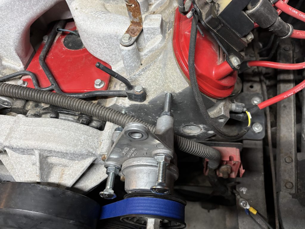
I went through a few different approaches, but settled on putting the tensioner on the left-hand side head. One bolt goes all the way through the tensioner and bracket plate, and threads into an accessory hole in the head. The other two bolts thread into threaded couplers that are welded to the bracket plate. The bracket plate is attached to the head with the all-the-way-through bolt, plus two shorter ones.
I learned the tensioner has a range marked on it so you can see if the belt is the right length. (In a stock application that shows if the belt has stretched beyond its service life.) There are 3 marks, minimum, ideal, and maximum. The best case is the mark on the pulley side lining up with the ‘ideal’ mark on the base side. I measured and used Dirty Dingo’s helpful length chart, and got it right on the second try. It’s definitely in the OK range, slightly on the small side of ideal, but as it will probably stretch with some use, it should settle in a little more.
Stock location for tensioner on right-hand side head
Cardboard template transferred to 3/16″ steel
Fist test fit of plate
Mocked up with random bolts and spacers to verify alignment
Final mockup with real spacers and threaded couplers
Tacked in place with horrible flux-core MIG welds
Welding finished, slightly less ugly, cleaned, painted
Belt fits!
Tensioner shows between ideal and small end of range
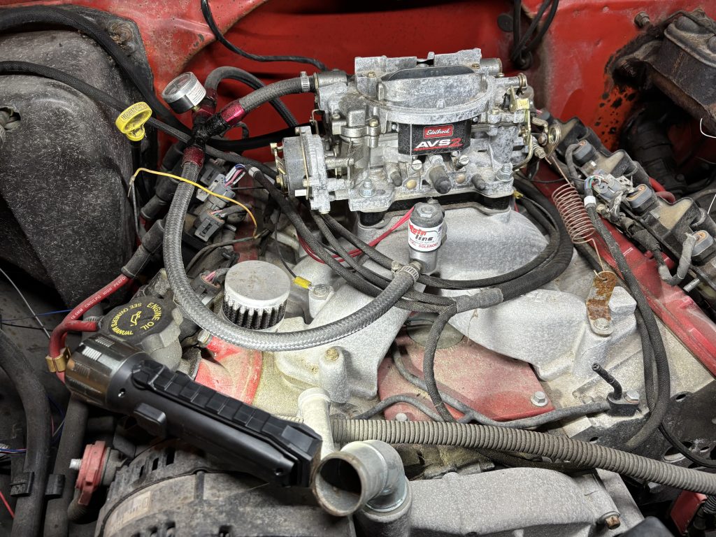
Although I had drained the ancient fuel from the tank, and cleaned the carburetor, the engine was running worse and worse every time I started it. I realized that there was no fuel filter on the truck, which was bad enough, but it was particularly bad given the condition of the old bad gasoline. I added an inline filter, cleaned the carburetor out…again, and it went back to starting and running smoothly again.
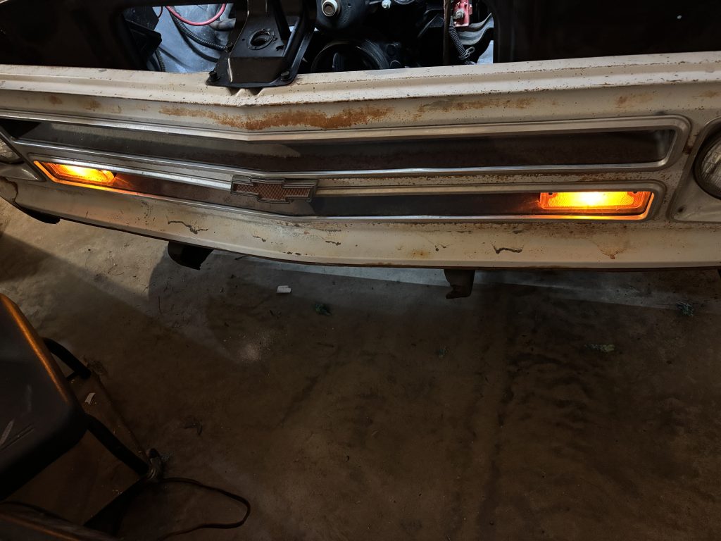
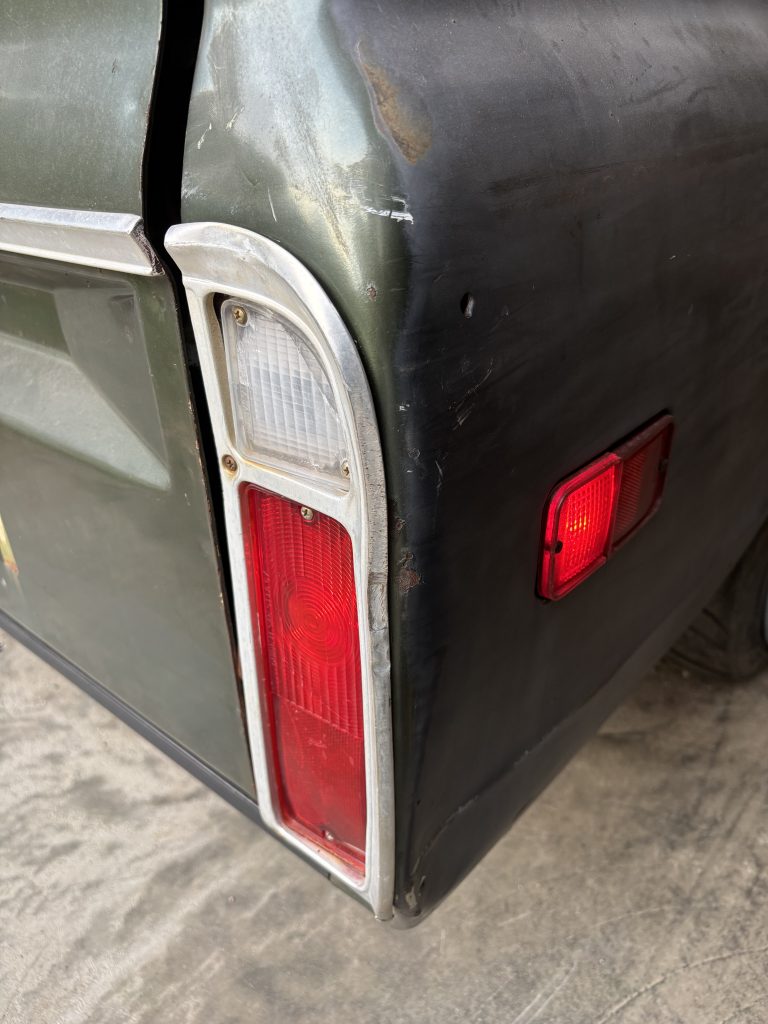
The LH marker/turn lamp did not work at all, and the RH one only worked for the turn signal element. I took the lens off of the LH marker and discovered there was no bulb in it at all. I could not get the new bulb into the socket, so I unbolted it from the grille. Unfortunately I broke both of the studs in the process, so I had to drill out the studs and replace them with bolts. The spring-loaded contacts at the bottom of the socket were not moving freely, which explained why I couldn’t get a new bulb in. After some PBBlaster and wire brushing, I got it cleaned up enough to accept the bulb. The RH side I managed to only break one of the two studs, so I only had to drill out and replace one of those. There was a bulb in the socket, but it was very discolored and obviously not in usable shape. It was also corroded into the socket, making it very difficult to remove. I sprayed it down with PBBlaster and let that soak. To remove the bulb, I put some heavy duty duct tape around the end of a tube and taped it to the bulb. After working it around for a while I finally convinced it to come out. A pass with a wire brush shined all the contacts back up, and the new bulb went in. Both the marker and turn lamps work now.
I was pretty sure the dimmer switch was bad, so I ordered a new one in the last batch of parts. I tried cycling the switch a bunch of times to see if I could get it working. The low beams worked, but the high beams did not. When I was trying to unplug the original dimmer switch, it broke and fell apart, so it was good that I had the replacement. The new switch worked the same as the old one, low beams worked but not high. I knew one of the bulbs was bad, so I had ordered replacements for those also. After replacing both bulbs, they both work on high and low beam.
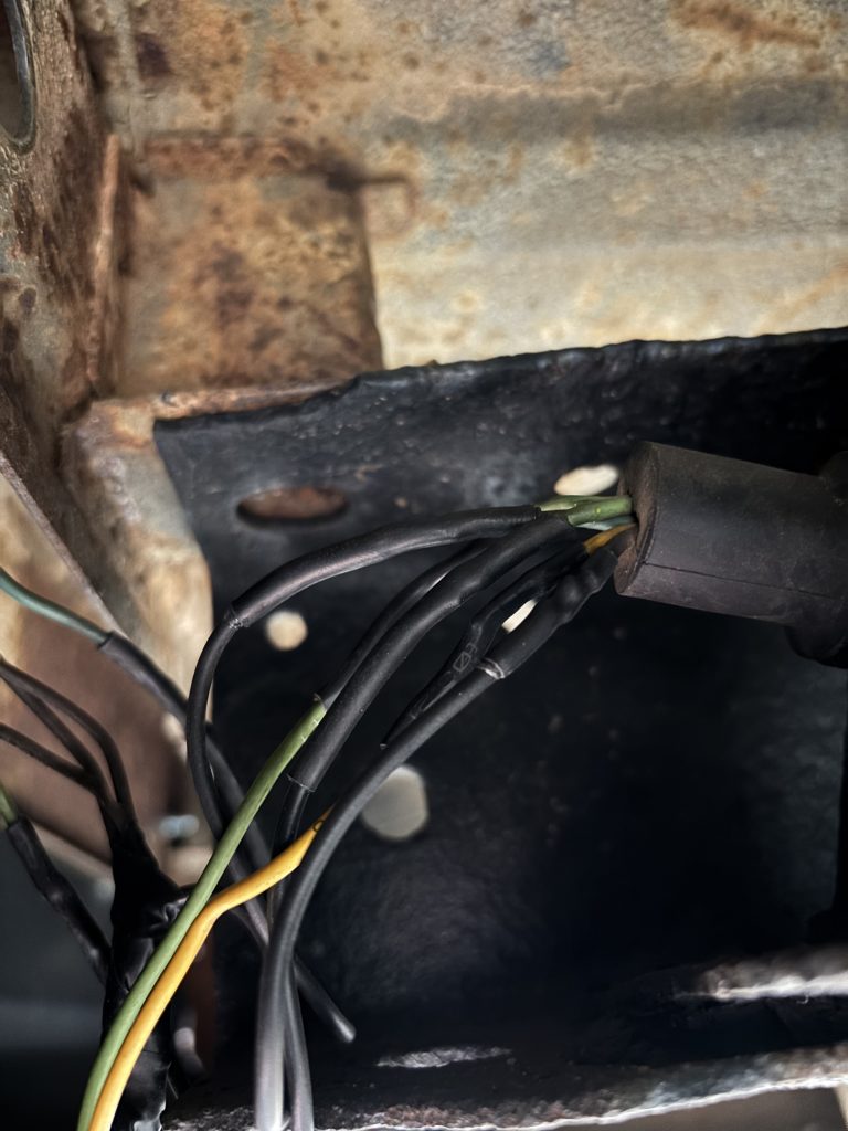
The rear harness plugs into a socket on the frame, Unfortunately, someone had cut all the wires and used butt connectors to repair that. A couple were connected, but most of the wires had torn apart. I spent a couple of hours stripping wire ends, and splicing in soldered connections to make it all work again. I don’t have a way to check the reverse lights yet, but the brake/turn and running lights are working again,
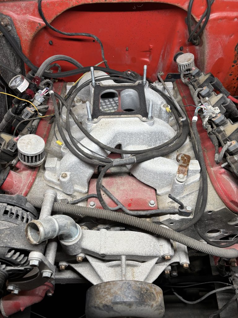
A friend set me up with a belt tensioner, so I started to figure out what to do with it. Originally it went on the upper right on the engine, but that is where the alternator is now. I was happy with the battery wiring to the alternator and starter, so I didn’t want to move that. There are two mounting holes in the front of the left head, but they are not in the correct plane for the belt to line up properly. I mocked up a mount using some long bolts, and got the belt path worked out. The tensioner needs to be oriented so the 3rd mounting hole is up in the air with nothing behind it. The tensioner is too strong to be supported by just two bolts screwed into the head, so I am going to try to make a bracket that will bolt to the front of the left head. My plan is to use thickwall tubing (actually an old alternator mount spacer from an SBC) to space it out 1.5″ from the head. I’m not sure if the bracket will pick up that 3rd mount hole, or if I will cut that off. The belt works out to be about 60″, and that looks ok as far as what lengths are available from the parts store.
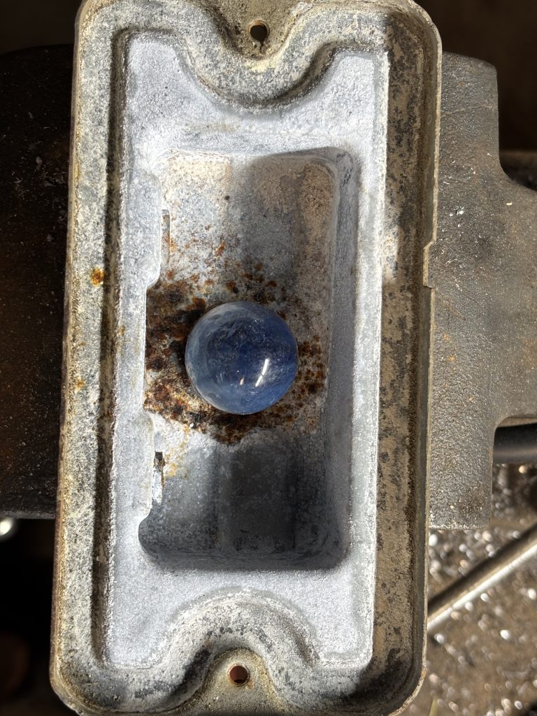
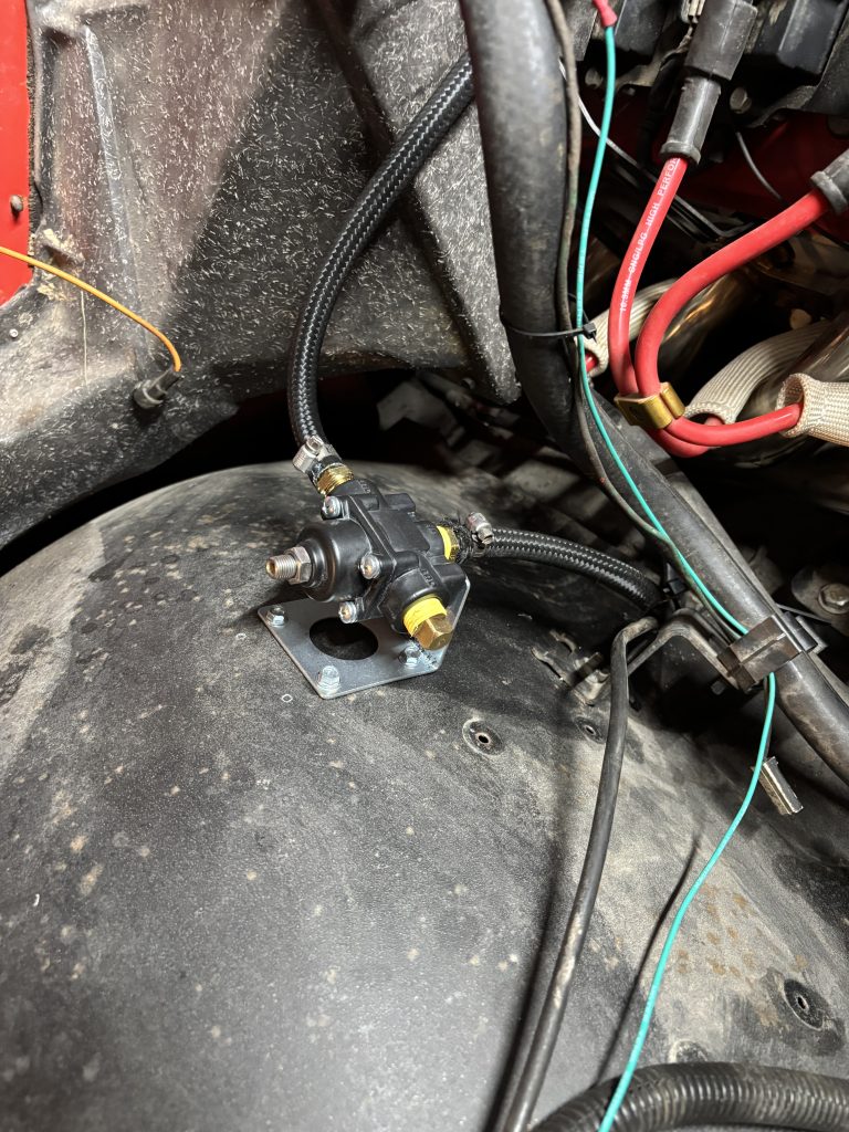
At first I thought the Gasoila had sealed the joints properly, but then after a couple of days it sprung a leak again. I went to the hardware store and got brass replacements for the two hose connections and the plug. I also got yellow sealing tape that is designed for use with gasoline, instead of the white teflon tape that I had tried before. Don’t use the white stuff with gas.
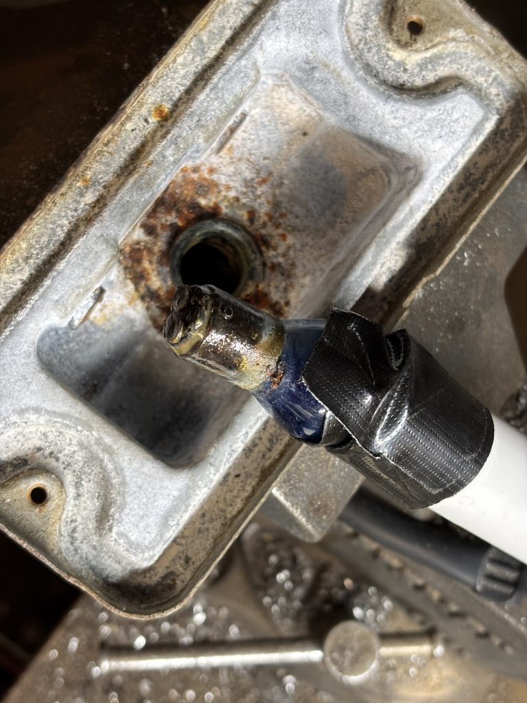
When disassembling things to put the new fittings on, the line from the regulator to the carb cracked. This will have to be replaced, but for now I cut the line shorter. Unfortunately that meant it was really a little too short for the distance, and I could only use one mount screw for the regulator. New hose is on the shopping list.
During some of my electrical tests, I had the key on, and I noticed that the fuel pump was running a lot, and not sounding like it was meeting with any resistance. I checked the fuel pressure gauge on the carb line, and…it was pegged at 15+ PSI. I’m not sure if the regulator has failed, if there isn’t enough fuel left in the tank, or if the gauge is bad. I ordered another gauge, and will go from there.
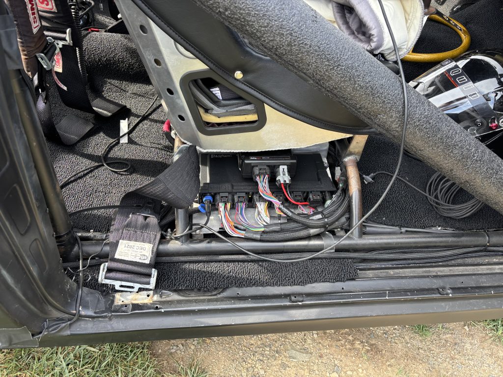
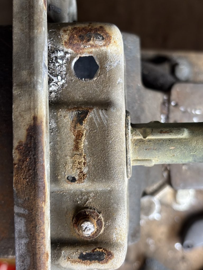
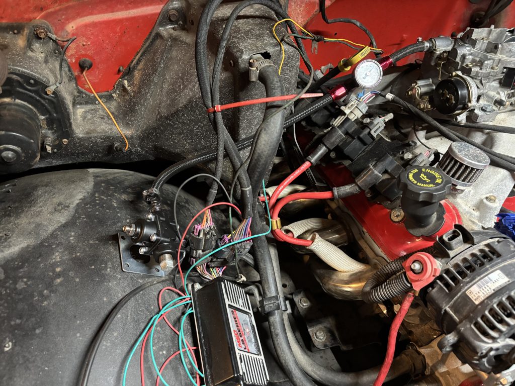
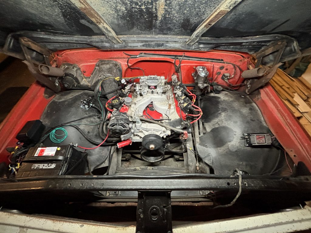
The fuel regulator ended up wanting to be right where the ignition box was mounted. Additionally, the wiring looms for the ignition were looped around the carb and just laying on the intake.
I decided to move the ignition box to the left inner fender, and leave the regulator alone on the right. The looms were long enough to be able to tuck them behind the engine, and then behind the fender mount point on the inner fender. This hid them and kept them safe.
The green wire is still TBD, so it’s not tucked away. It is the signal to turn on the fuel pump and ignition box power relays. Currently it’s connected to the old coil+ wire because I assumed it would only be active in the start and run positions of the ignition switch. I discovered it’s also active in the accessory position, which makes no sense to me. I’m still deciding how to get a better circuit to drive these that is not active in that position.