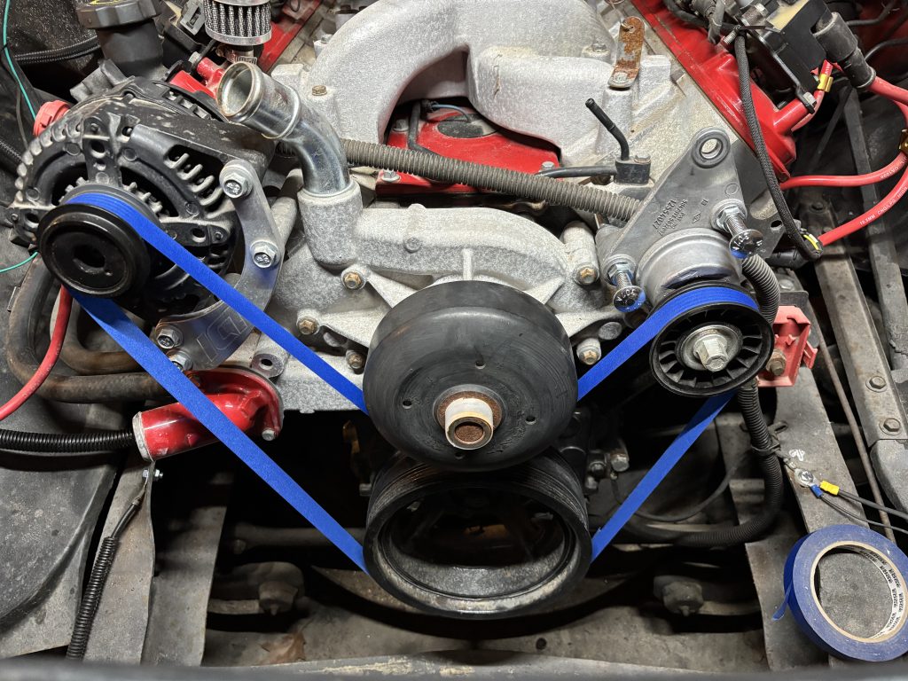
The next problem to be solved was the serpentine belt drive. This setup has no air conditioning or power steering, so the belt just needs to drive the alternator and the water pump. PO installed the alternator with an aftermarket ICT bracket, in front of the right hand head. This placement worked well, except that it took the location where the belt tensioner is in the stock configuration. I decided to move the tensioner to the left hand head in a mirror-image orientation. I could not find an aftermarket bracket that mounted the tensioner on the left, so I made my own. It’s not pretty, but it gets the job done.
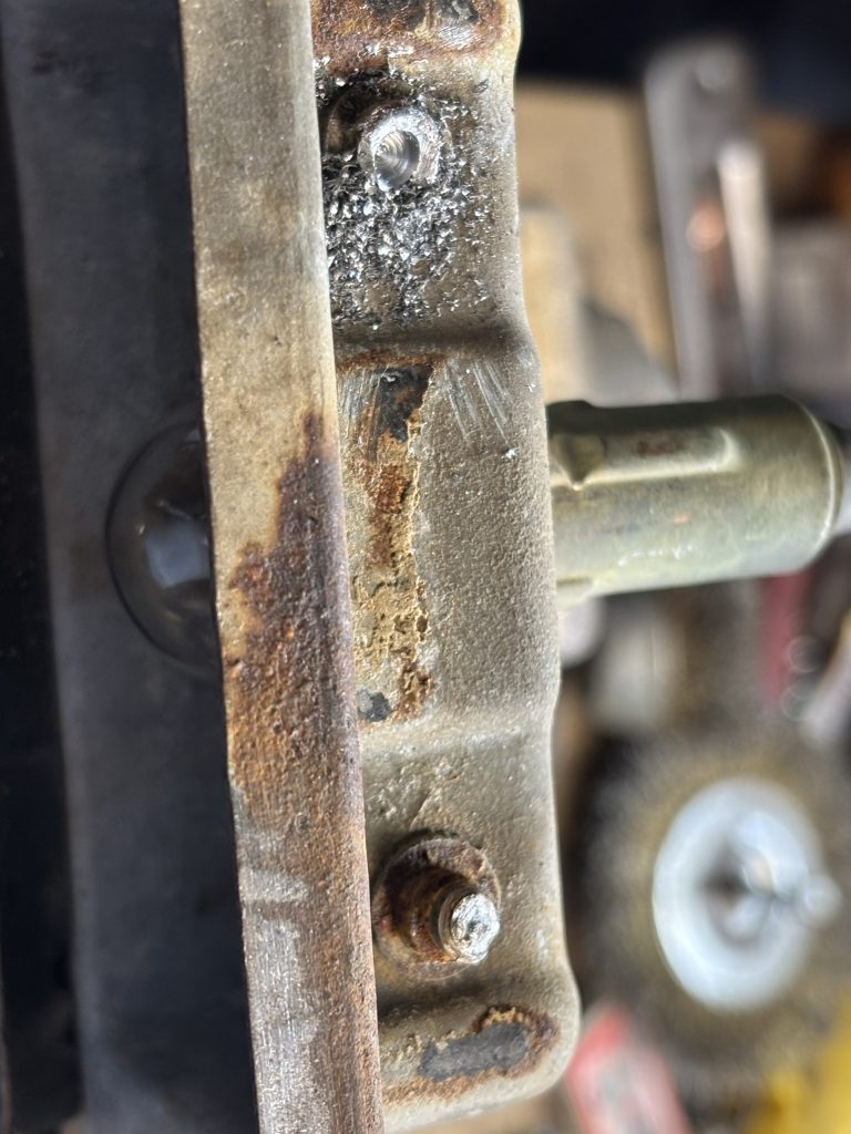
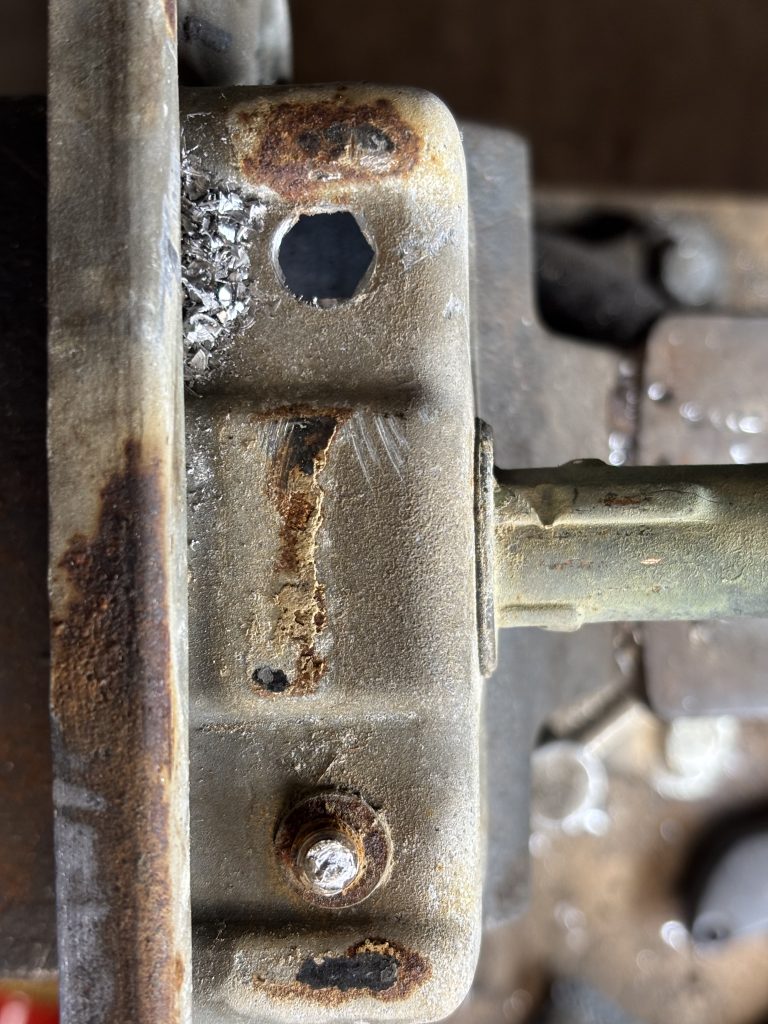
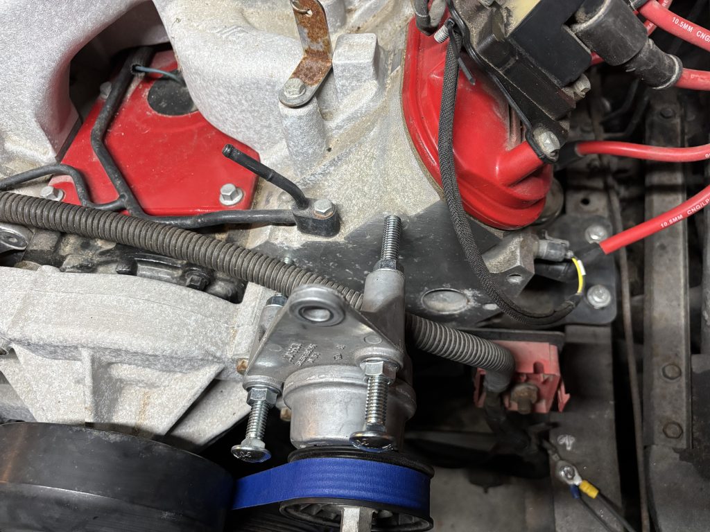
I went through a few different approaches, but settled on putting the tensioner on the left-hand side head. One bolt goes all the way through the tensioner and bracket plate, and threads into an accessory hole in the head. The other two bolts thread into threaded couplers that are welded to the bracket plate. The bracket plate is attached to the head with the all-the-way-through bolt, plus two shorter ones.
I learned the tensioner has a range marked on it so you can see if the belt is the right length. (In a stock application that shows if the belt has stretched beyond its service life.) There are 3 marks, minimum, ideal, and maximum. The best case is the mark on the pulley side lining up with the ‘ideal’ mark on the base side. I measured and used Dirty Dingo’s helpful length chart, and got it right on the second try. It’s definitely in the OK range, slightly on the small side of ideal, but as it will probably stretch with some use, it should settle in a little more.