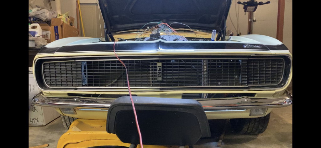
The original RS headlight door setup is complicated, unreliable, and expensive. 1967 was an electric system, 68 and 69 were vacuum-operated. You can purchase aftermarket reproduction parts to re-create those. There are also a couple of aftermarket retrofit kits available.
Here’s a relatively inexpensive retrofit that will operate the doors if you are not concerned about originality.
Parts
The core of the retrofit is the controller and motors from a 4th gen (1993-2002) Firebird.
Parts list – 4th gen Firebird:
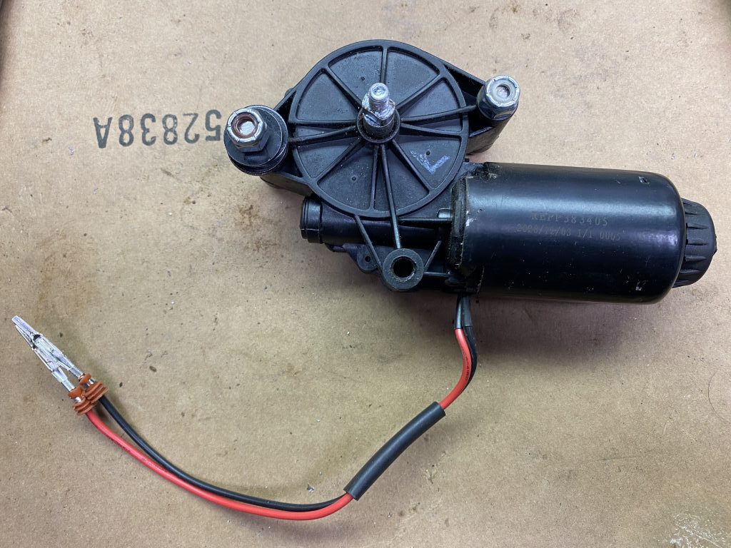
– Pair of new replacement motors – $80
– Used headlight controller module – $70
– Used headlight wiring harness – $35 (optional)
Miscellaneous:
– 3/16″ steel scrap for motor drive adapters
– Nuts, screws, washers for attaching motors
– two 10mm M6/1.5 nuts for motor shafts
– wire + connectors
– two inline fuse adapters with 15A fuses
The replacement motors are easy to find at auto parts stores or eBay. I used the ones for the same model Firebird as the controller just to make sure everything is compatible, but a power window motor or a headlight motor from another vehicle should work also.
The controller module can be purchased new, but they are getting more expensive, and I found a good used one on eBay for much cheaper. The controller works by running the motor until it senses the motor is drawing more current (because it has hit something) and then it will cut the power to the motor. That means there’s no adjustments or timing to figure out, just hook the motor up to the doors and they’ll move until they hit the full open or full closed position.
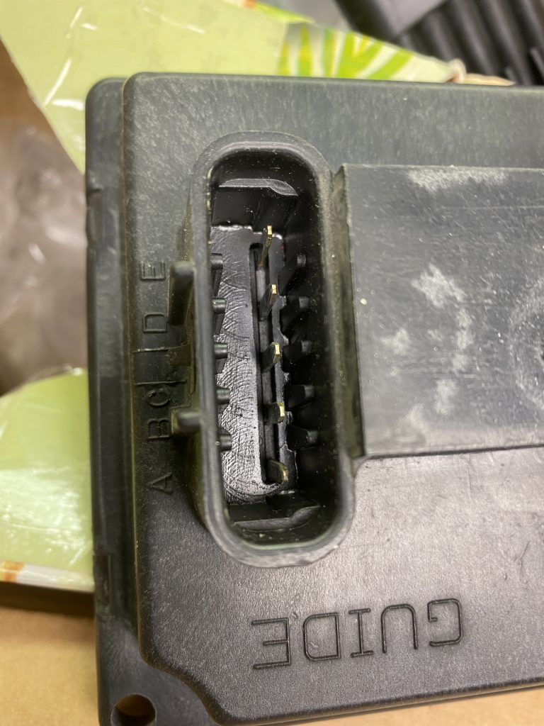
The wiring harness is optional. It was an easy way to get the 4-position and 5-position connectors that plug into the controller module. You can buy them new, they are metripack connectors.
Wiring
Here’s what the original Firebird schematic for the headlights looks like:
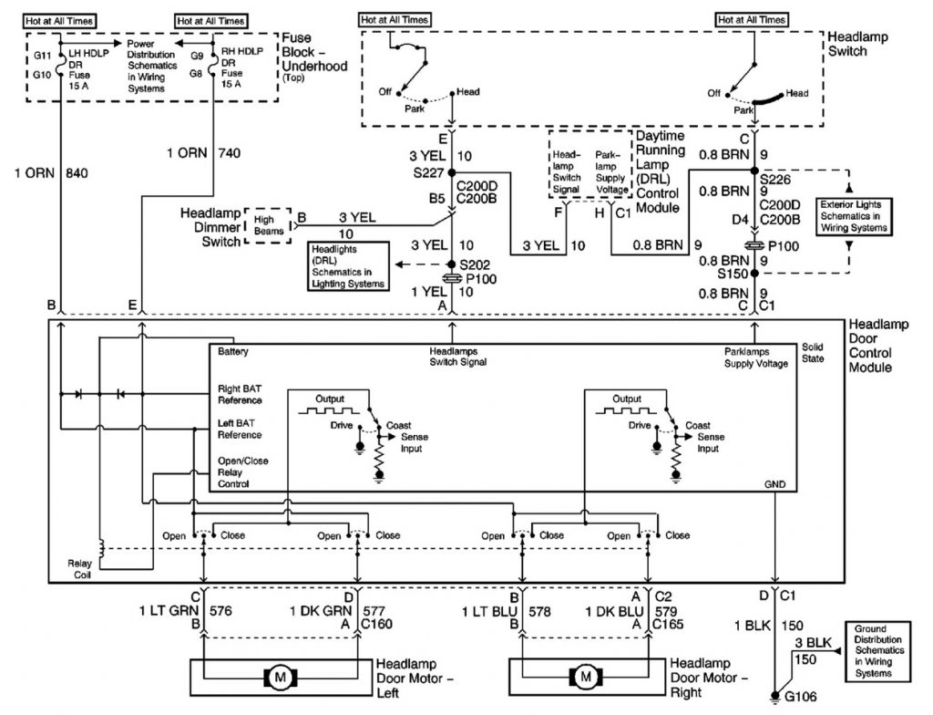
A few things to note from the schematic:
- There are separate power feeds for the two motors. The schematic shows that each one has a 15A fuse. The benefit of having two separate fuses is that if one fuse blows, the other side will still work.
- The controller module has relays inside it, so it is not necessary to add a relay or additional fuse between the controller and the motors.
- The connector 1 position C wire is OPTIONALLY connected to the parking lights. The normal behavior in the original Firebird application is that the lights pop up when the headlights go on, but they don’t retract until the parking lights go off. The original Camaro setups (both vacuum and electric) had no connection to the parking lights, and only trigger on the headlight signal. If you want it to behave as original, connect it to ground. If you like the Firebird operation, connect this to the parking light power. (Note that if you don’t connect it to anything, the doors will stay open all the time.)
- The schematic shows the controller connected directly to the headlight and parking light circuits, so it is not necessary to add a relay or additional fuse to these connections.
The basic wiring consists of:
5-position connector #1 labeled ABCDE
– A1 – Headlight power signal – light blue wire between headlight and dimmer switches
– B1 and E1 – Always-on power through separate 15A fuses
– C1 -ground for Camaro behavior, connect to parking lights for Firebird behavior.
– D1 – ground
4-position connector #2 labeled ABCD
– A2 – Black lead motor 1
– B2 – Red lead motor 1
– C2 – Red lead motor 2
– D2 – Black lead motor 2
(I’m not sure if the wire colors are consistent on all replacement motors, but if the doors open with the lights off, and close with the lights on, swapping the red and black will fix that.)
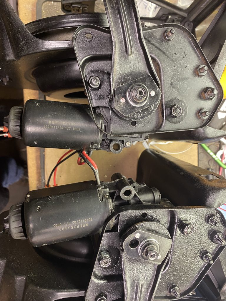
Motors
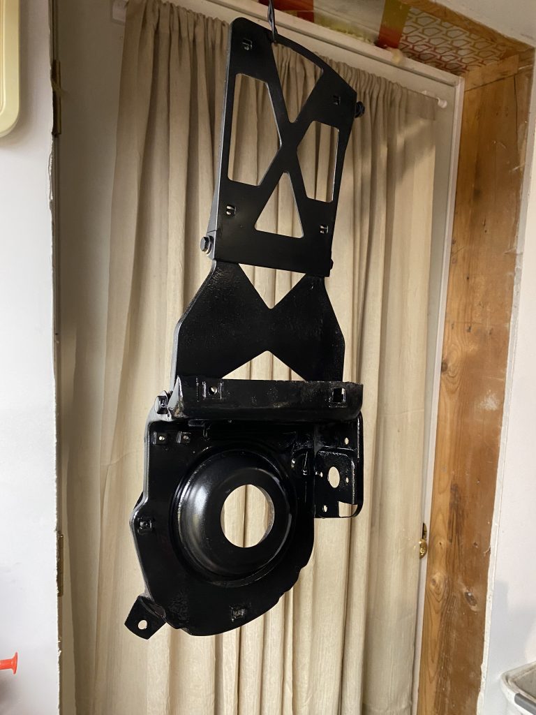
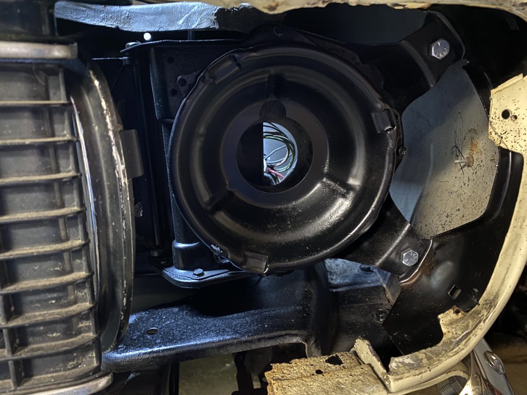
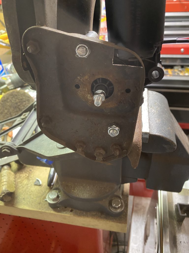
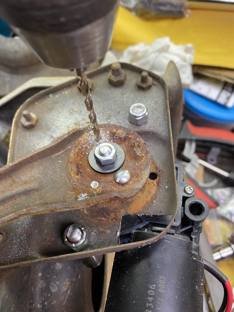
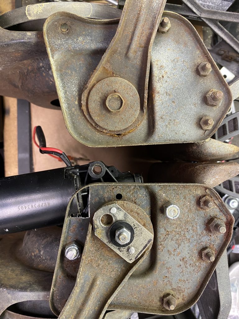
The motor is attached to the headlight housing with two bolts and some spacer washers. The placement is a bit of a compromise between centering the shaft in the hole, and leaving enough clearance for the motor and the gearbox.
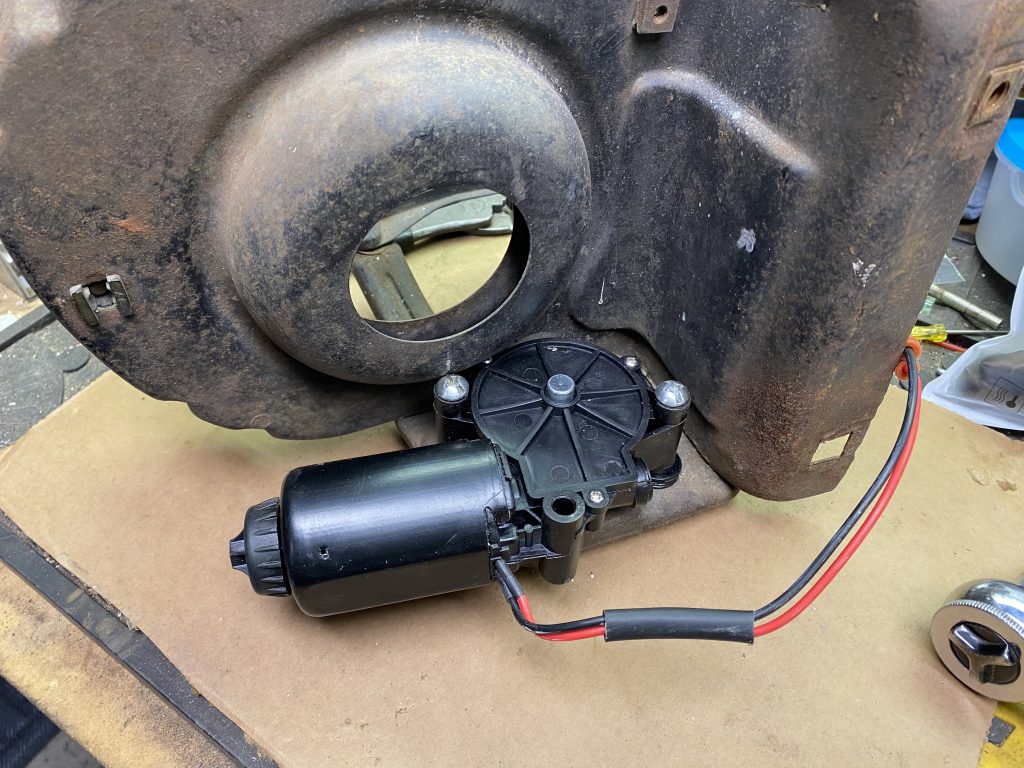
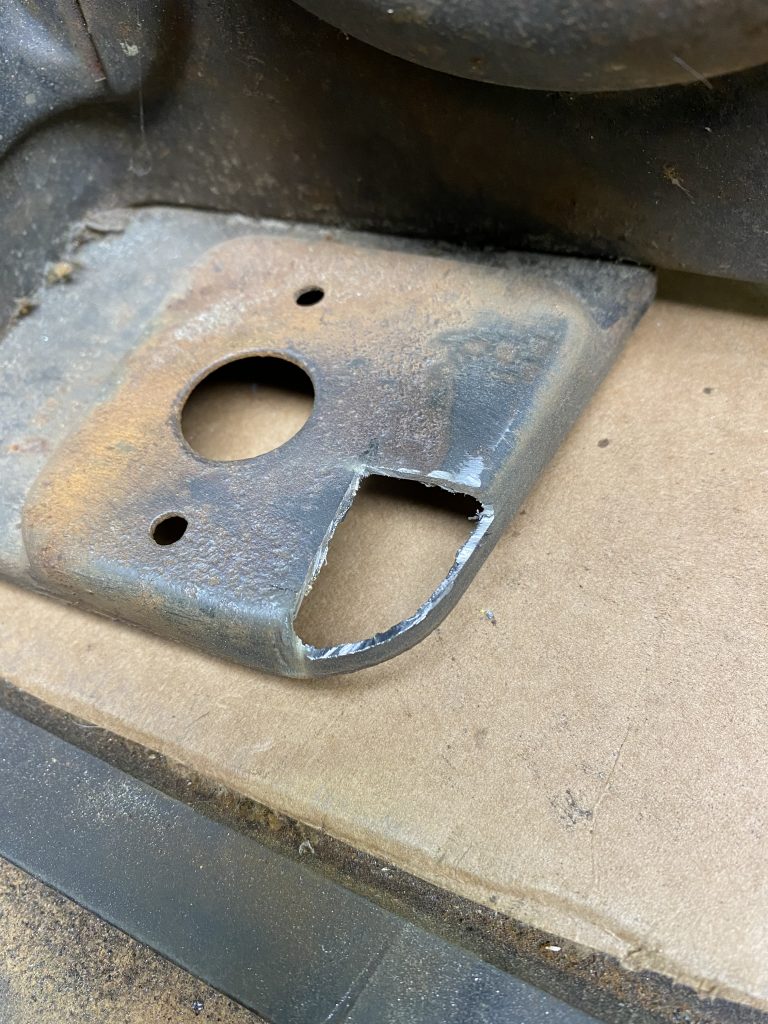
With the motor in the right orientation, it hit one corner of the bracket. Cutting a clearance notch allows the motor to sit level.
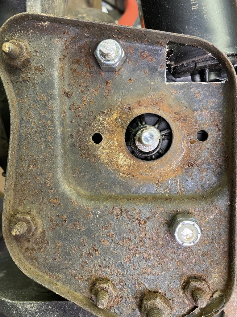
In order to get the holes lined up as accurately as possible, I marked and drilled one hole, then bolted the motor on, and then marked the second hole.
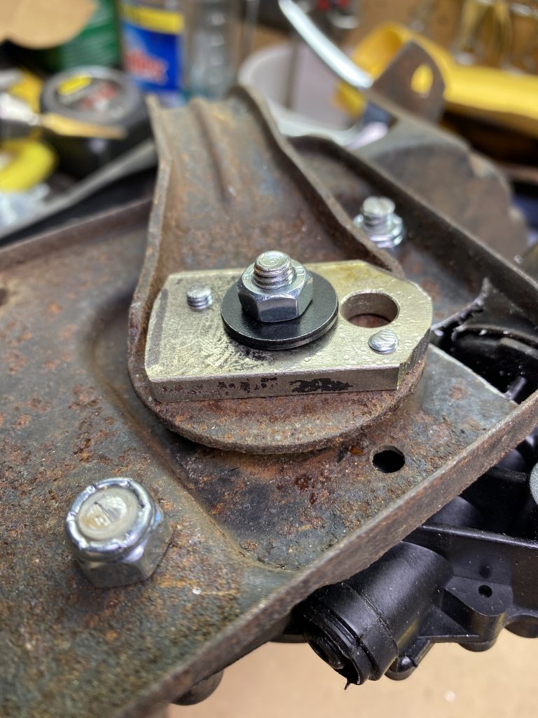
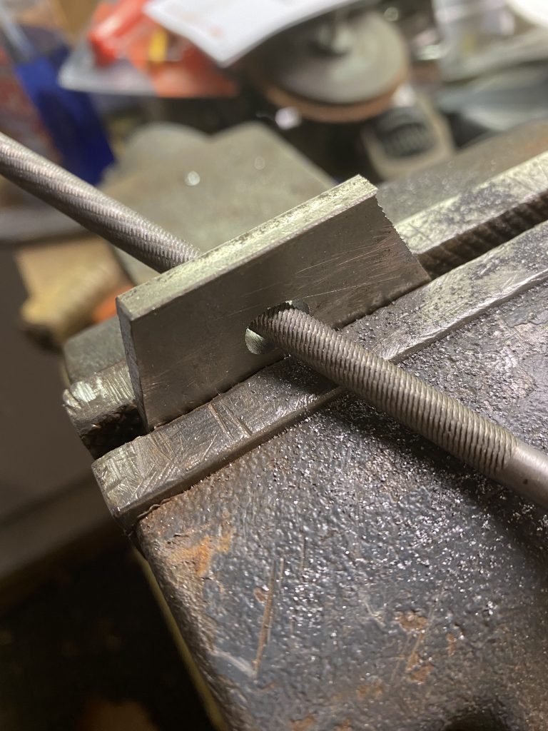
Attaching the Arm to the Motor
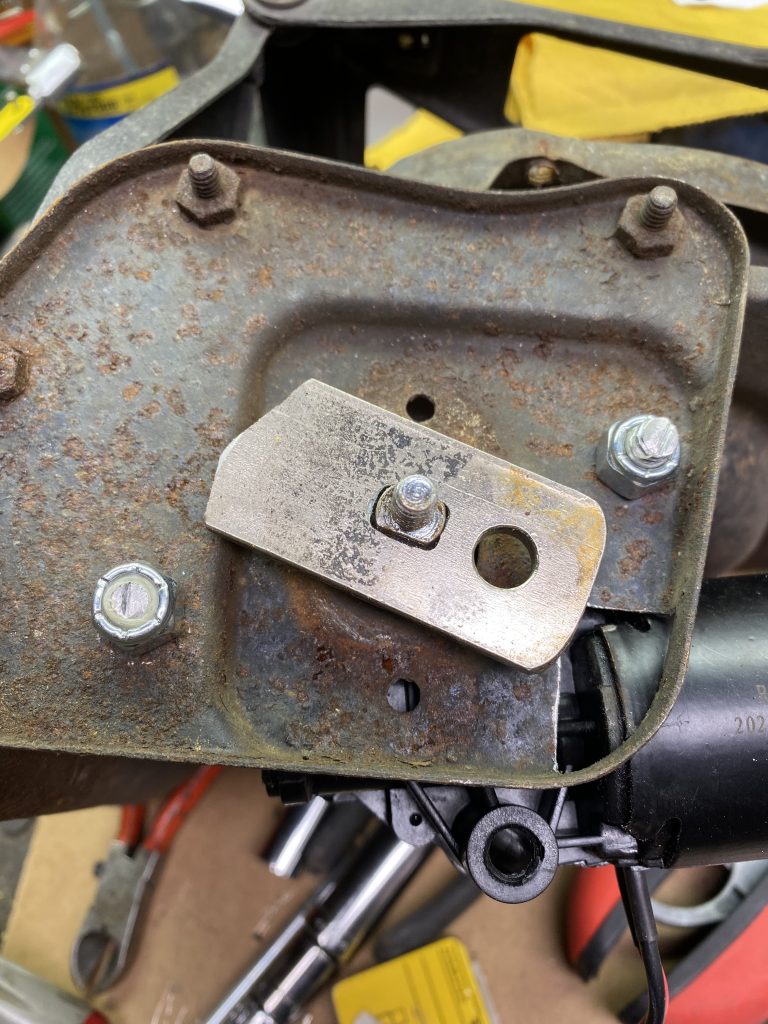
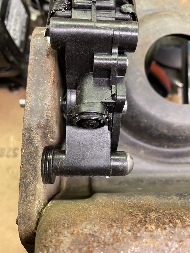
The bellcrank arm has a hole in the center that is almost the same size as the shaft on the motor. The shaft has two flats on it that provide surfaces to turn the arm. Unfortunately, the original bellcrank hole is too big to make a satisfactory matching oval hole out of. I used a piece of 3/16″ scrap to make a plate that had the oval hole in it, and then attached that to the bellcrank with a couple of screws. This spreads out the load and also allows it to sit lower on the shaft, which is closer to the stock location relative to the bracket.
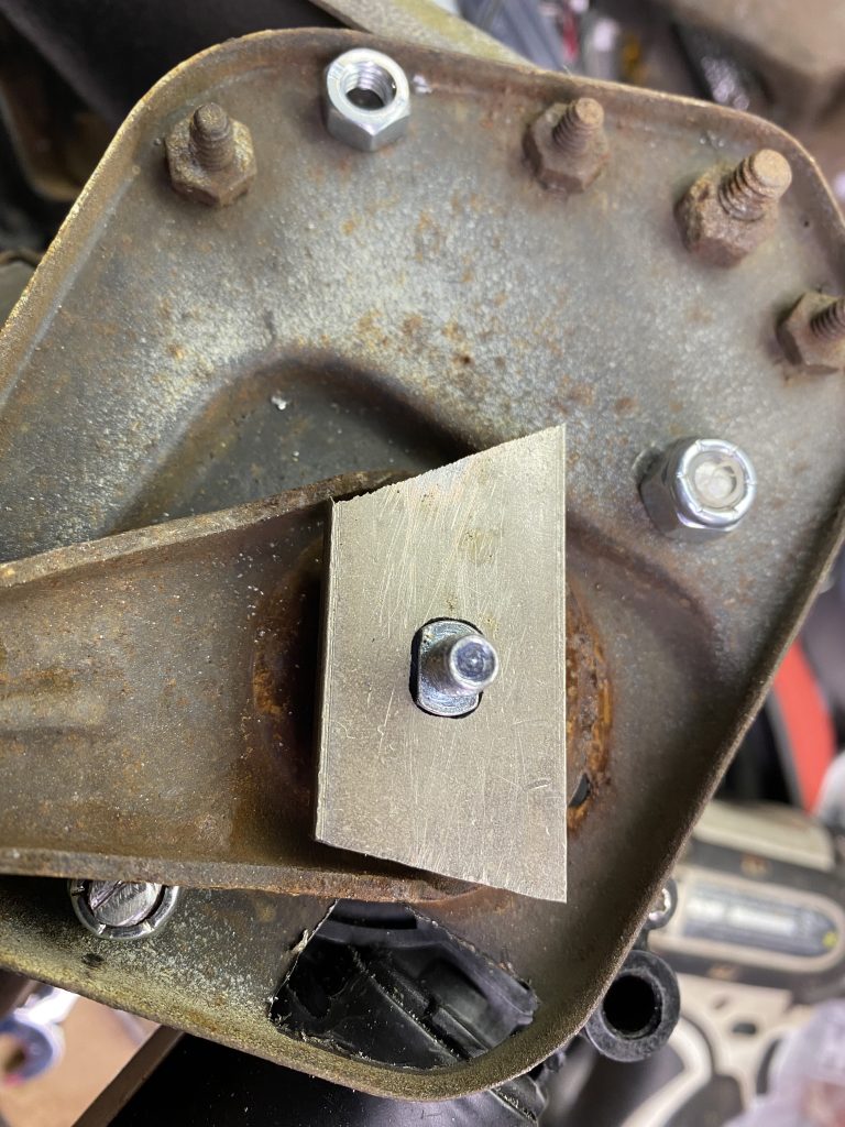
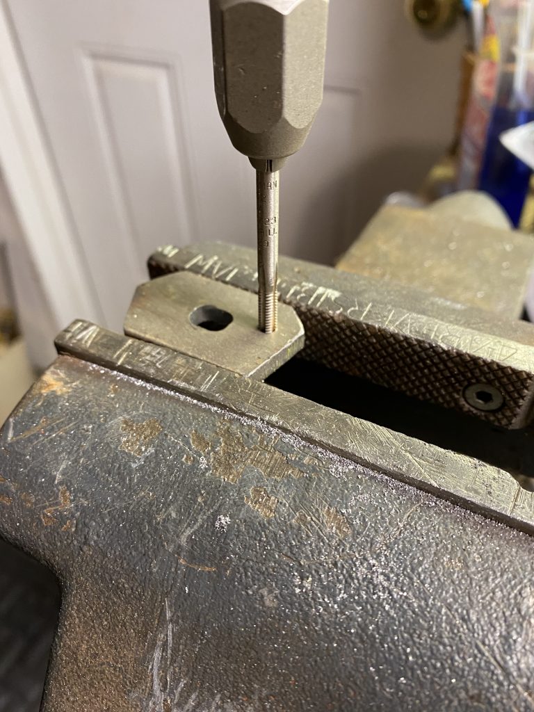
To add the holes to the plate, I drilled and tapped one hole, then assembled it temporarily and drilled the second hole.
After the holes are drilled and tapped, I screwed the plate to the bellcrank arm from the back side so it would sit closer to the housing. Assembling it in that order leaves some room underneath that prevents the arm from hitting the inner fender support structures.
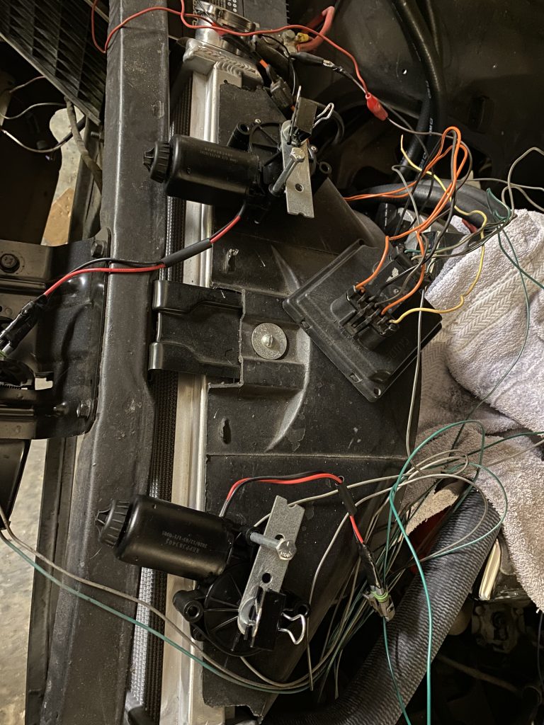
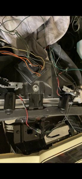
Mounting the Controller
I used a couple of sheet metal screws to attach the controller to the radiator support just next to the regulator
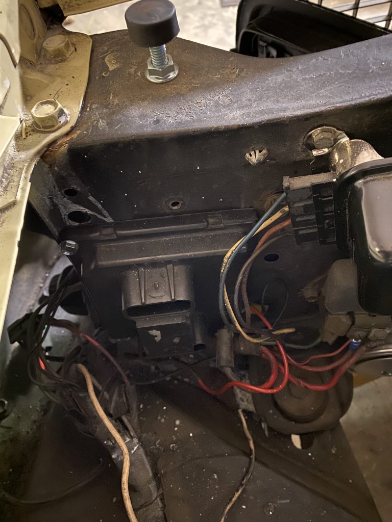
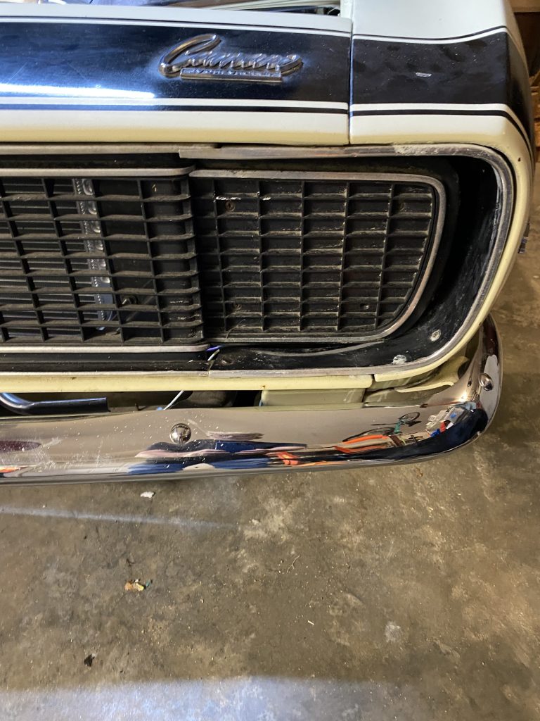
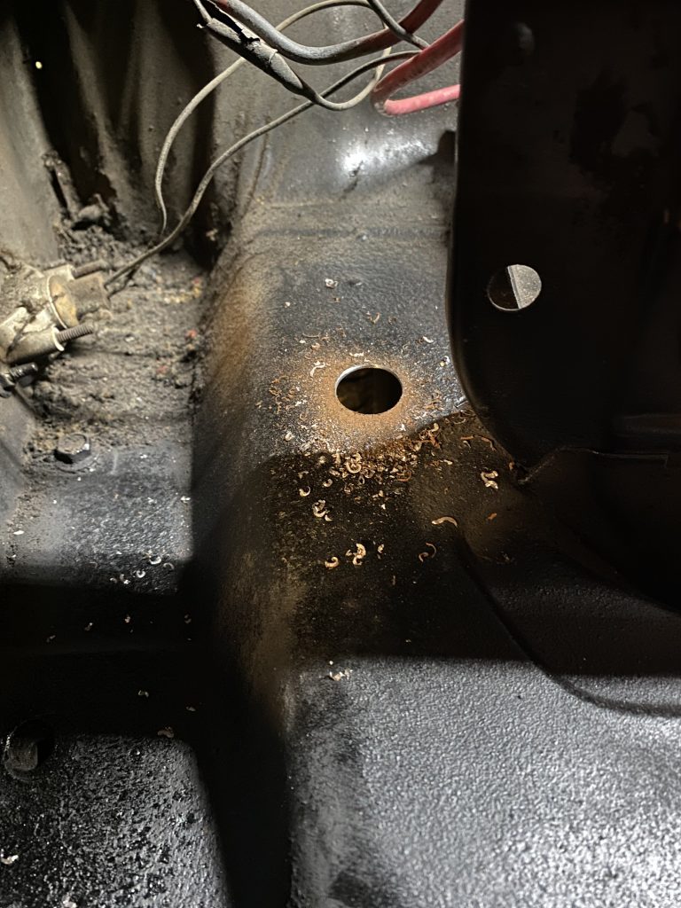
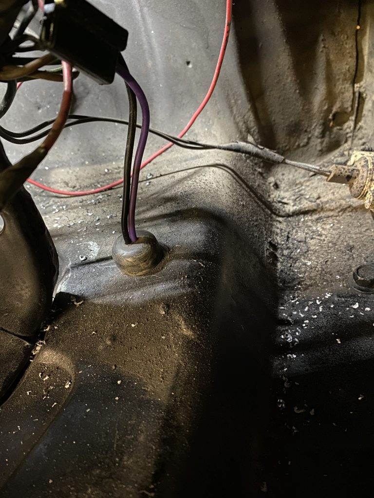
One last detail was moving the RS turn signal wiring. The wiring had been run through the area where the headlight doors move, and would interfere. The stock wiring harness goes through a hole in the inner fender. I drilled the holes and rerouted the wiring.
Final Assembly
I did all of the modifications and test assembly using the original rusty dirty parts. I did clean things up and paint them before installing them on the car for the final time.