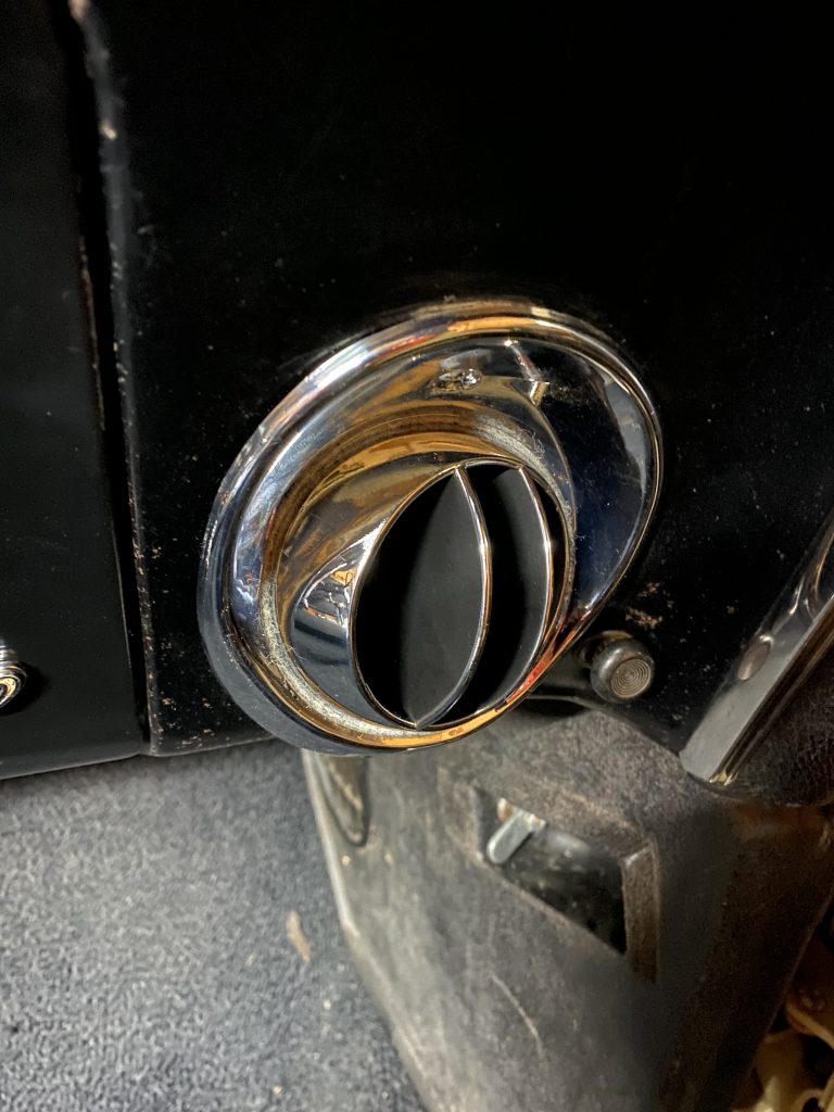
I don’t know why exactly, but the astro-ventilation assemblies always fascinated me. They really seem like an important part of the dash design, and not just an afterthought.
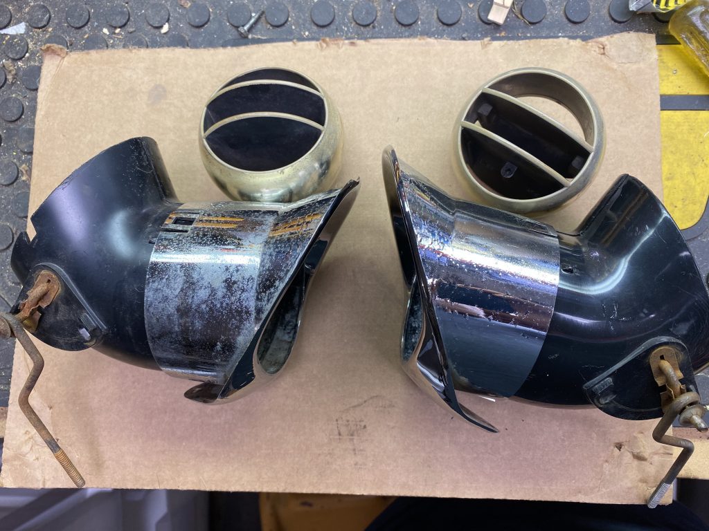
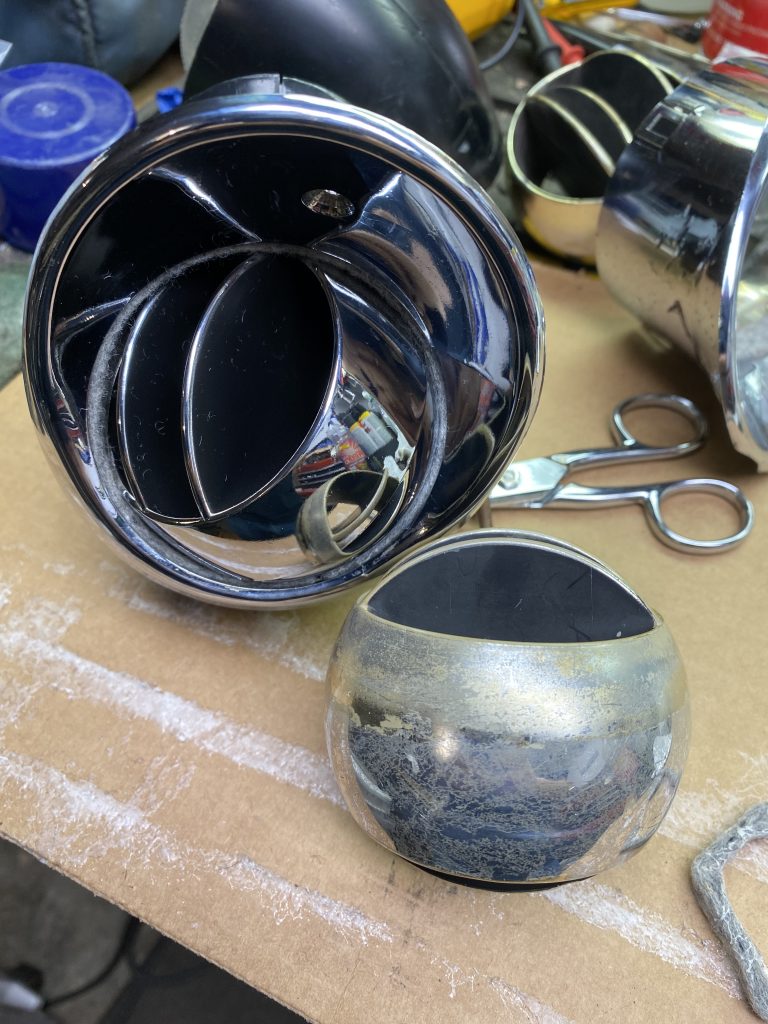
The ones in the car had seen better days, they look like they are original pieces. The housing was in very good shape, the chrome on the bezel was all intact and smooth, but the felt seals had turned to dust a long time ago. The chrome on the ball parts was in pretty bad shape, probably about half of it had worn off entirely. I purchased new aftermarket balls, and a felt seal kit. The new pieces were not exactly like the old ones. Most notably, the new ones had a distinct separation line around them, while the originals were all smooth.
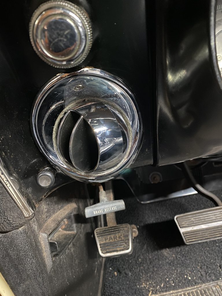
The first step is disassembling and removing the housings. There are two screws on the bezel, one at 12 o’clock, and another one at 6. The bottom screw goes directly into the dash metal, but the top one goes into a short curved metal bracket that pinches against the back of the dashboard. You don’t technically need to take the top screw out all the way, just loosen it up a lot until the bracket is loose. If you take the screw all the way out, make sure you don’t lose track of the bracket. The two screws are different length, the short one goes on the bottom, and the longer one goes in the top hole.
The control knob next to the housing unscrews, leaving a threaded rod. This is the same as the door lock knob if you need to replace it.
The natural thing to do is to pull the housing out of the dash, but that leaves the threaded rod stuck in its hole in the dash, which doesn’t allow it to come out. The trick is to pull it out just far enough that you can get the bottom of the housing to push back through the dash opening. Once it’s there, turn the housing 90*, which will pull the threaded rod out of its hole, then you can feed the whole assembly out through the front.
There is a short plastic oval flexible tube that connects the back of the assembly to the cowl vent. This may fall out as you take the vent assembly out, as there’s no fasteners on it, it’s just held in place by the vent assembly.
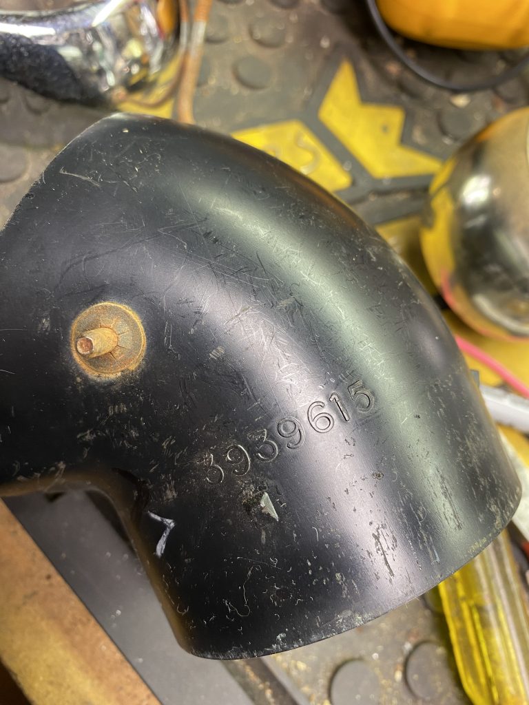
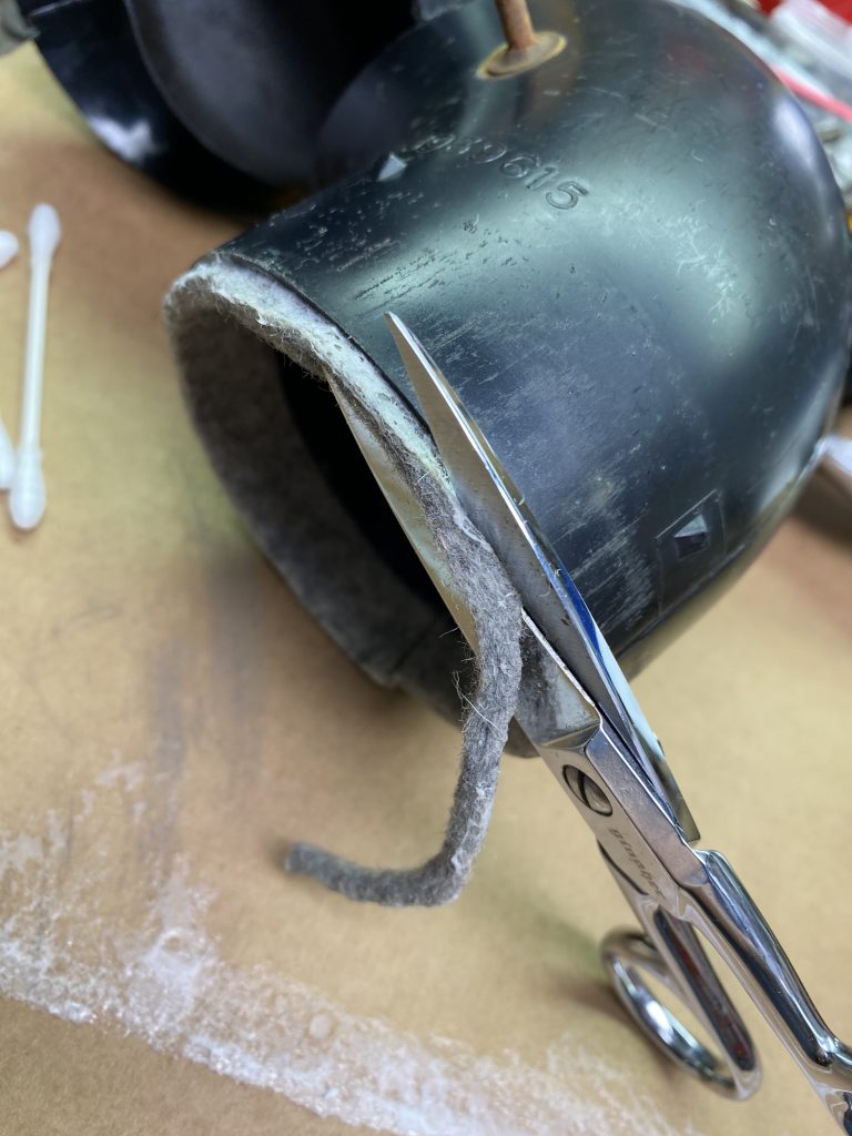
Once the assemblies are out, mark them left and right so you don’t get them mixed up. You can identify which goes on what side by the threaded rod lever is on. 3939616 is the RH one, 3939615 is the LH one.
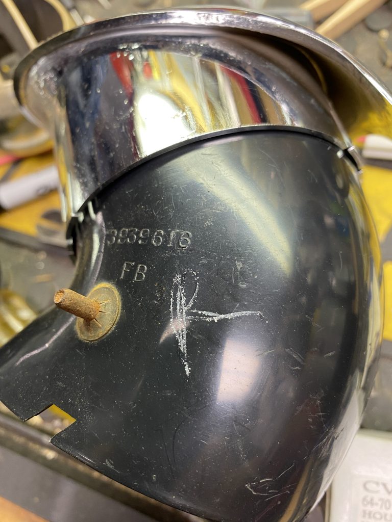
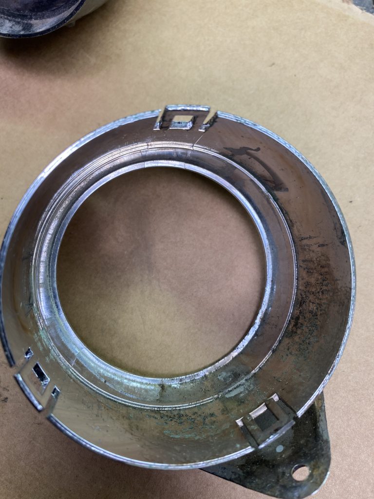
There are three tabs on the chrome bezel that fit over corresponding bumps on the black plastic back half. To disassemble these, you need to carefully separate the two halves, and gently pry up on the tabs to get them past the bumps.
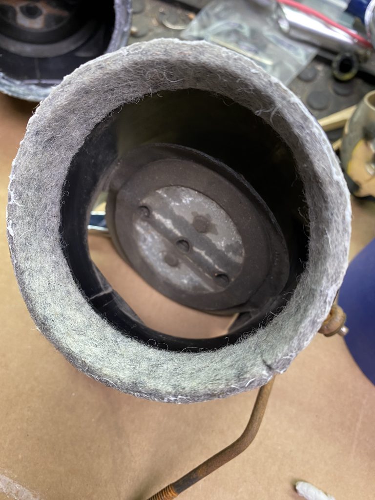
In my case, the flapper valve was in great shape, and did not need any repair. You may need to disassemble this part and add new rubber seals.
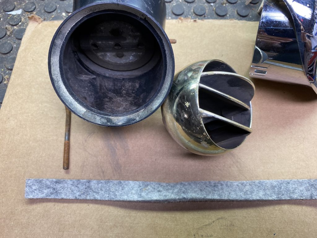
I used Permatex upholstery adhesive to attach the new felt pieces. This is the same glue I used on the headliner. It’s contact cement, which means you put it on both pieces, let it dry a little while, then stick the pieces together. It’s very sticky, and you only get one shot at putting the parts together, as it’s very difficult to separate them.
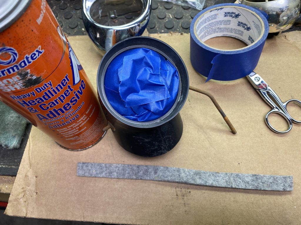
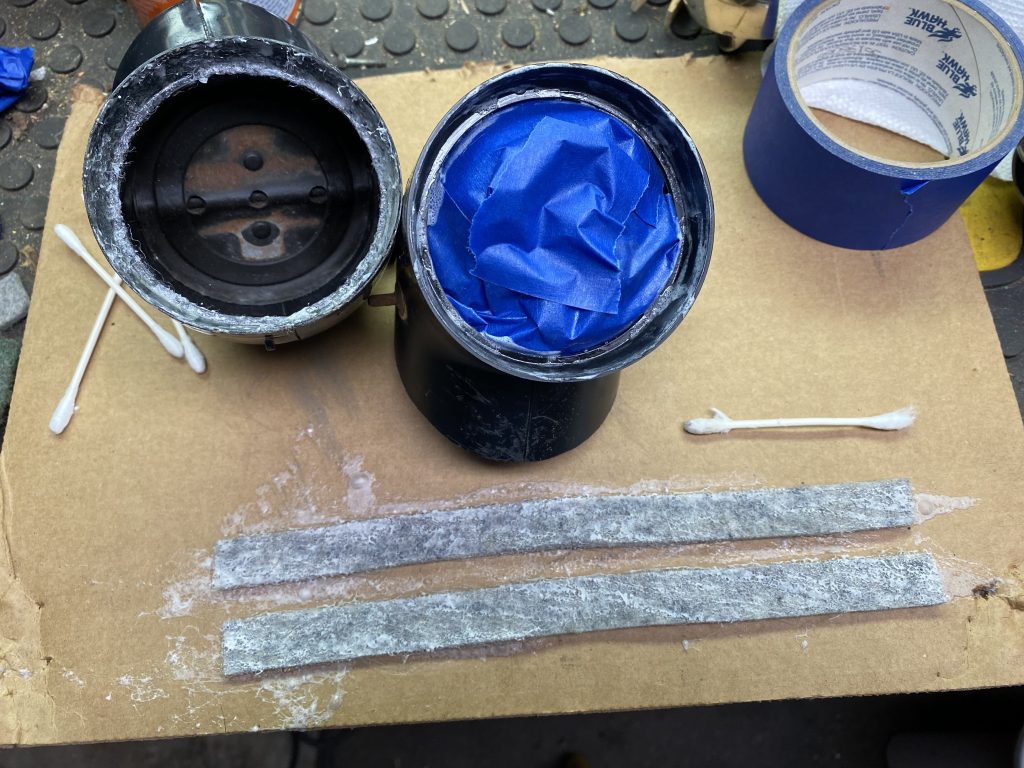
I sprayed the adhesive on the felt pieces, then sprayed a bunch of it into a baggie and used a q-tip to paint the adhesive on the housing surfaces. (Originally I had planned to spray the housing piece also, which explains the blue tape. I decided to try the q-tip, and that worked out much better. No tape required.) After 5 minutes I gave everything a second coat (per label instructions) and let it sit for about 10 minutes.
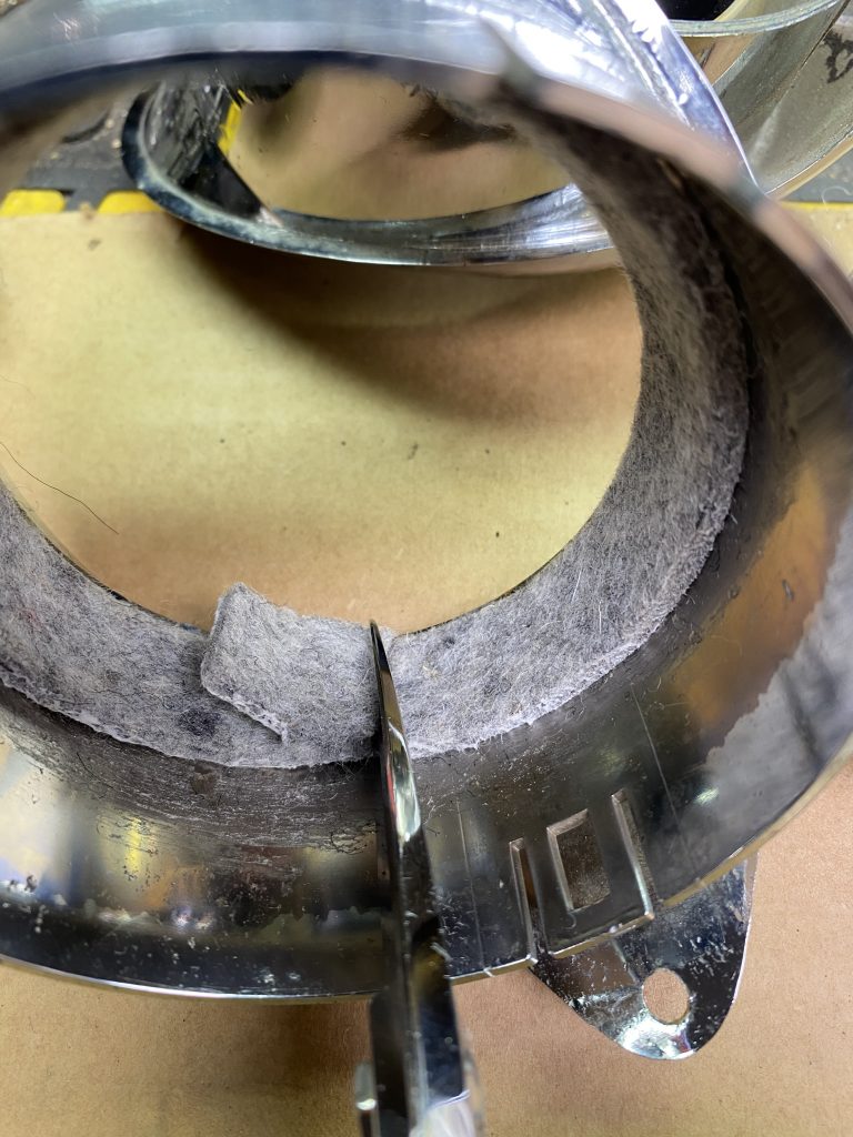
Once the glue had set up and was tacky, I carefully worked the felt strips around the housing mount surface, and trimmed off the excess when I got back to the start again.
I let this sit and dry for a day (per label instructions) before doing the final assembly.
On the black half of the housing, I used scissors to trim the felt flush with the edge of the plastic. On the chrome half, there wasn’t a good way to trim off the excess, so I just left it. It might be a good idea to trim these to the correct width before gluing them on, but it seemed to work with only the other half trimmed, so…maybe that’s not necessary.
Reassembling the housing is straightforward, put the ball in, and carefully press the two halves together until the tabs engage the bumps. Make sure everything works smoothly before continuing.
Putting the housings back in the dash is the toughest part of the job.
Good news: I think I have a promising second career as a contortionist.
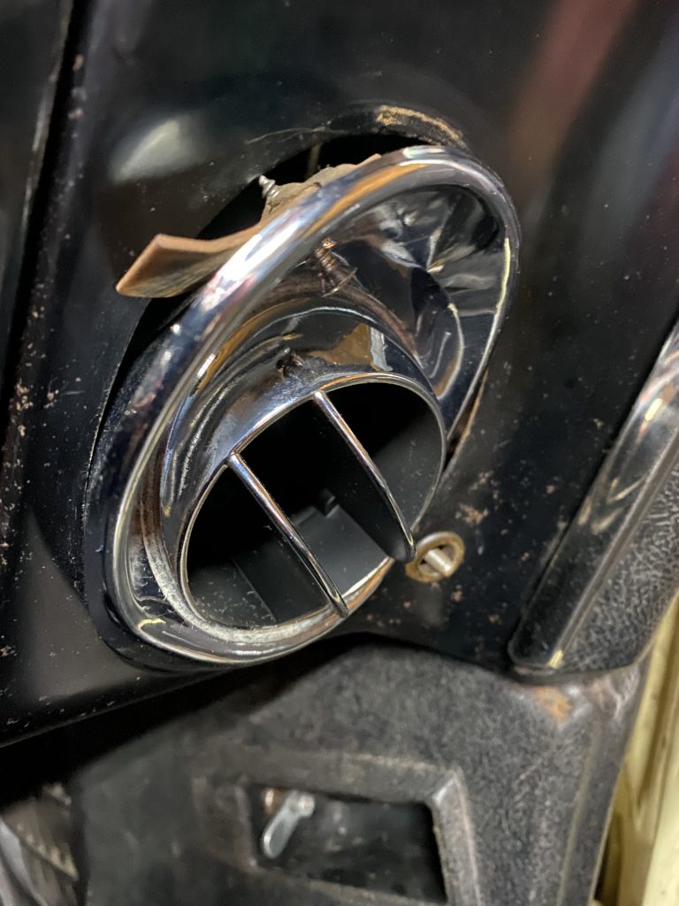
For the driver’s side, there’s zero room to get your hand up there with the parking brake assembly in place. It can be done without removing the parking brake! The surprisingly successful installation approach was to turn it 90* and feed the assembly from the front all the way through the opening so the bottom of the bezel was completely behind the dash, then rotate it upright again and tip the top edge back out through the opening while feeding the threaded rod through the ferrule.
The same process works on the other side. In this picture, the bottom edge of the housing is inside the dash, the top edge is out, and the threaded rod has been fed through its hole.
Continue pulling the assembly out until the bottom edge comes out. The oval flex tube joint goes on next, then align and tighten the screws. For the top screw, thread it through the bezel and into the metal clip, but leave it loose. Once you get it into place, use the screw to rotate the clip until it’s facing the right way (longer curved end up), then pull down on the bezel to pinch the clip in place while you tighten the screw.