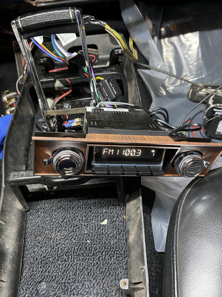
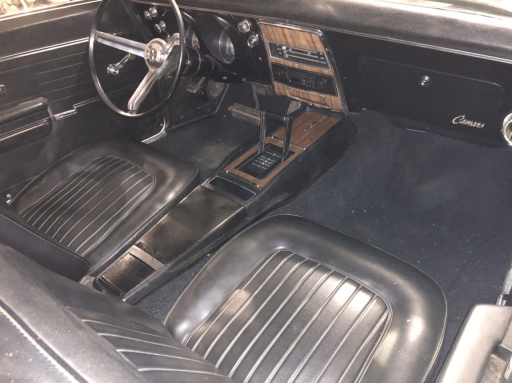
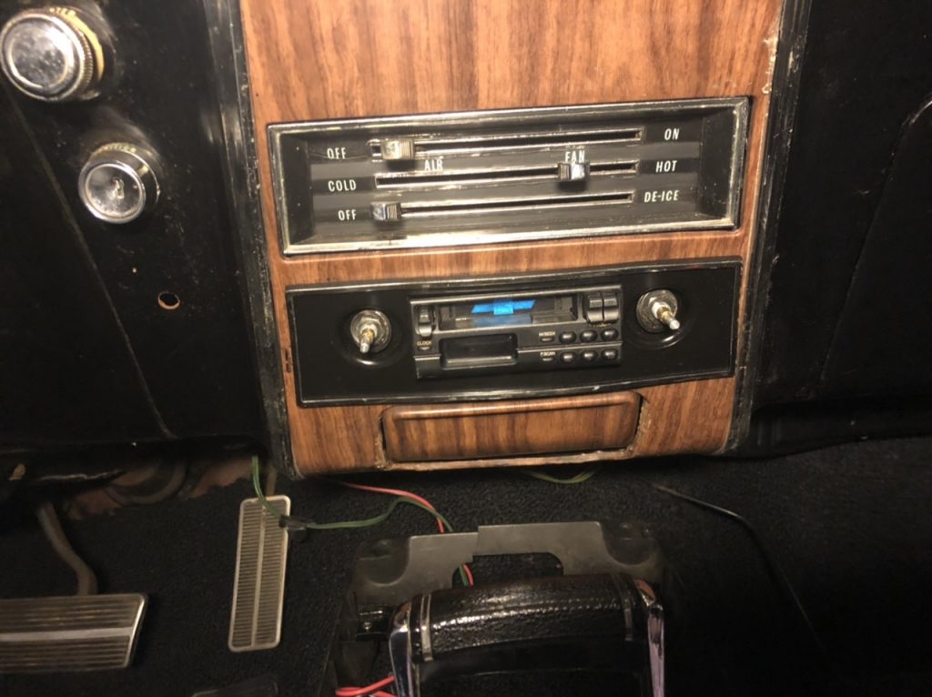
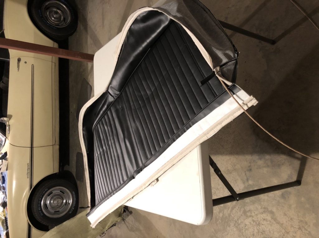
I got a Retrosound stereo for Christmas, so while I had the dash apart, I hooked it up:
I got a Retrosound stereo for Christmas, so while I had the dash apart, I hooked it up:
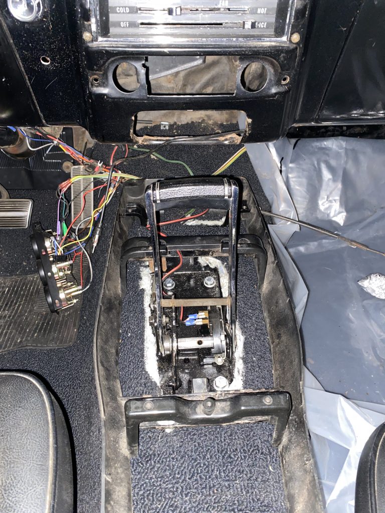
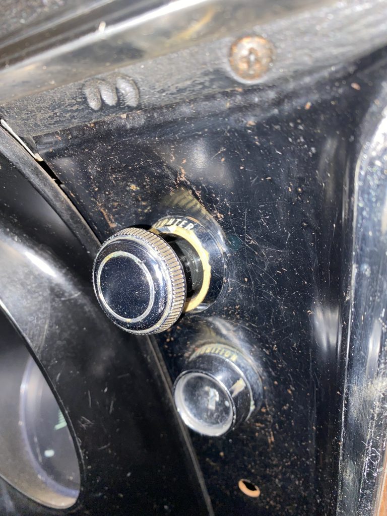
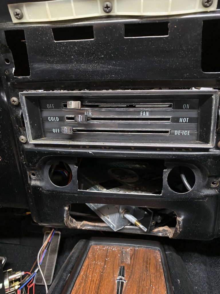
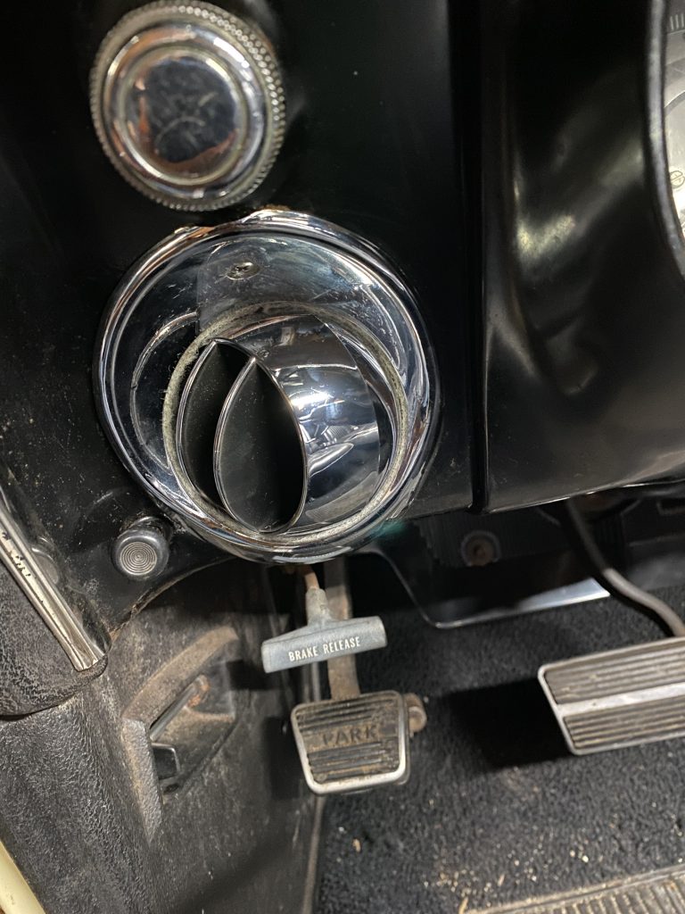
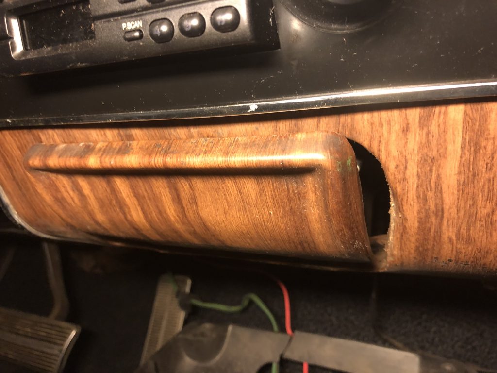
When I had the center of the dash apart to fix the heater controls, I also replaced the cigarette lighter socket. I don’t smoke, but I wanted the socket to work so I could charge my phone, or run a GPS.
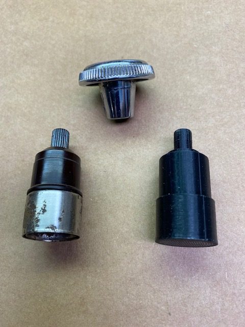
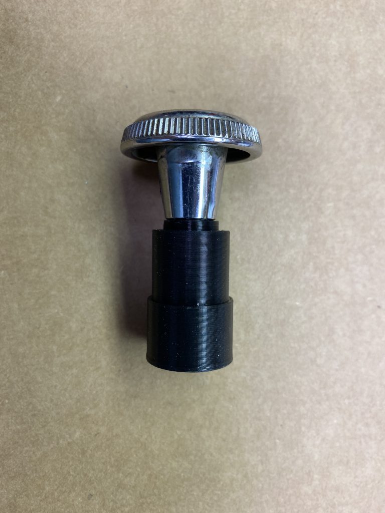
The lighter element was rusted into the old socket, so when I pulled on the chrome knob, it pulled off of the rest of the lighter. I didn’t want to put the old rusty element in my nice new lighter socket, so I made a dummy one to hold the chrome knob so nothing looked like it was missing. I created a 3-D printer design for this, which I uploaded to Thingiverse.
https://www.thingiverse.com/thing:5136514
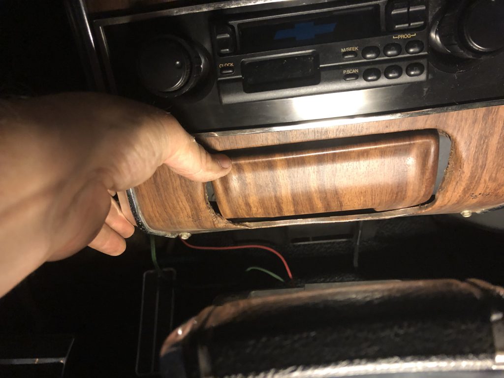
The final photo shows it in the dash, and the flash managed to highlight all of the dirt and scratches on the dashboard. It looks better in person.
Get the repair kit they said. It’ll be great they said.
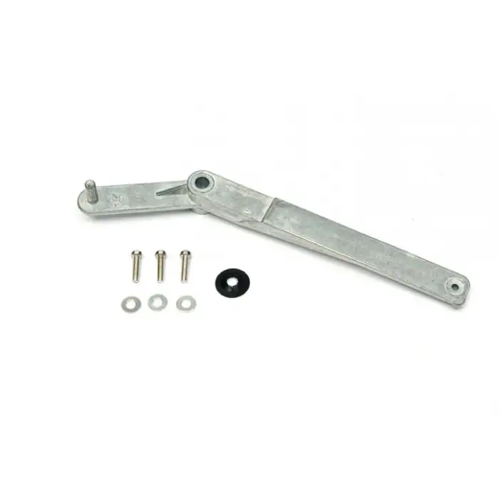
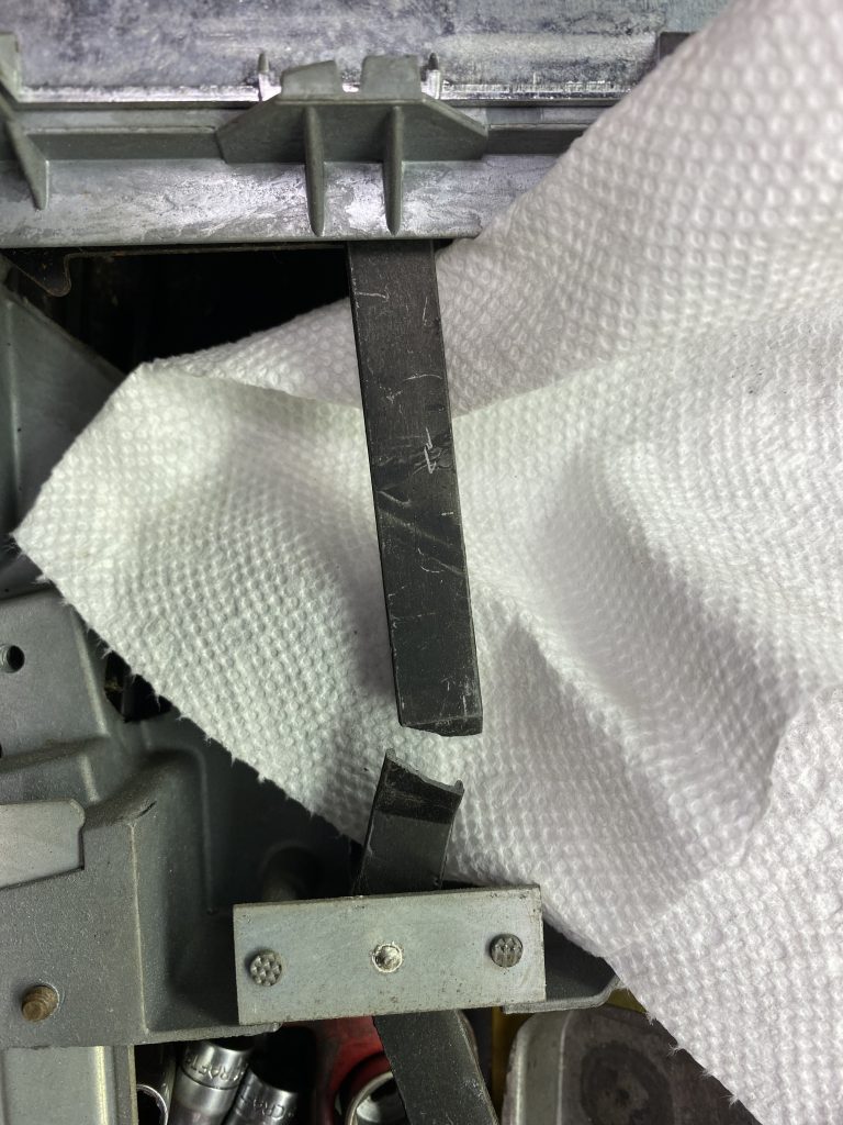
The kit consists of a new arm, and some screws to attach joints that were originally staked. The new arm is much beefier than the original one, so it looks like a good upgrade.
The disassembly process is pretty simple. The first step is grinding off the two staked pegs holding the pivot end plate.
The third point is the pivot at the end of the defroster lever. Once that is ground off, the old lever can be removed.
At this point, the instructions say to drill and tap the two pegs holding the pivot end plate. The supplied screws are 4-40, but it’s up to you to find the appropriate drill and tap. It turns out that is harder than it sounds. I hit several large box stores, none of them had anything that small. I finally broke down and hit eBay, and ordered a Du-Bro drill and tap set, intended for model hobbies.
It was shipped and supposed to arrive in the mail on Friday, so I figured I’d be able to work on it for the weekend. Wednesday it disappeared off the tracking, so on Friday I hit a real hardware store and found a 4-40 tap and the correct size drill to go with it. I drilled and tapped a test hole, but it turned out that the tap was UNC, and the screws were UNF. Friday night the package was on the tracking again scheduled for Monday.
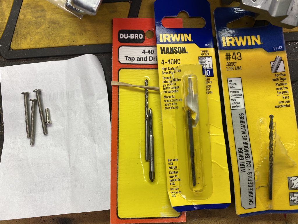
When it arrived, it turned out to also be a coarse-thread tap. I decided the universe was trying to tell me something, and I dug up some 4-40 coarse thread screws and used those instead of the supplied ones.
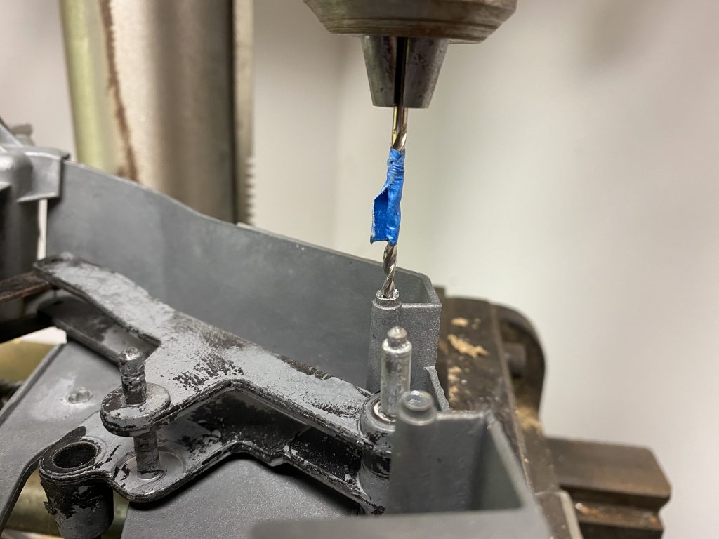
Drilling the holes. The tape marks the correct depth for the hole.
Tapping the holes
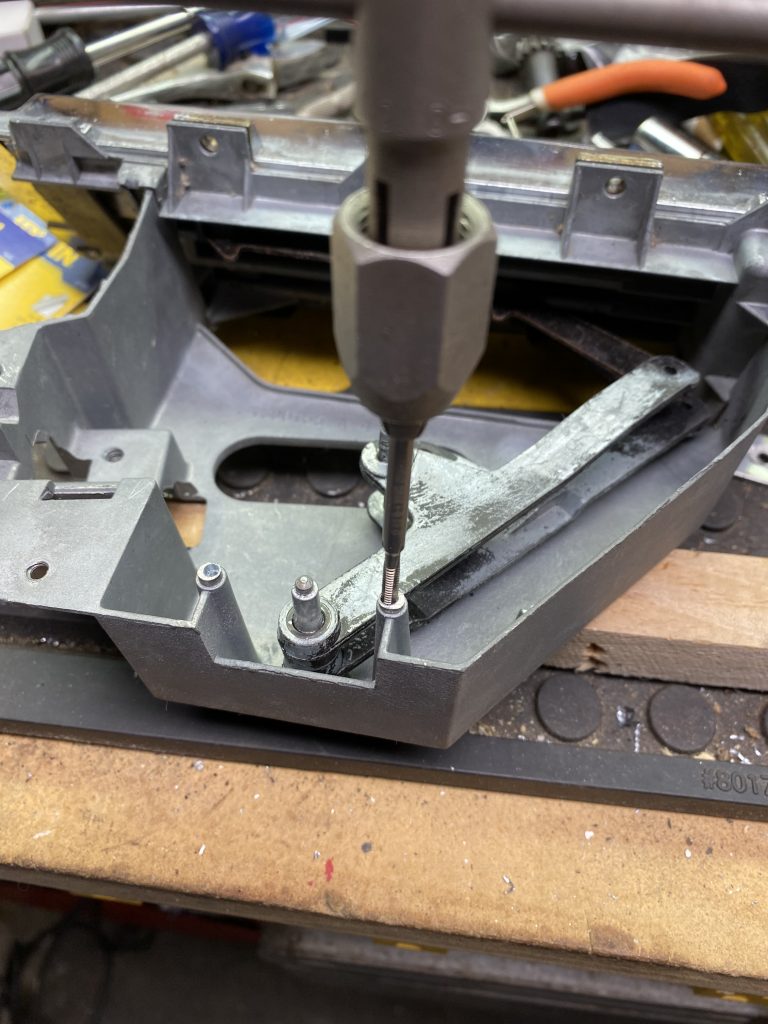
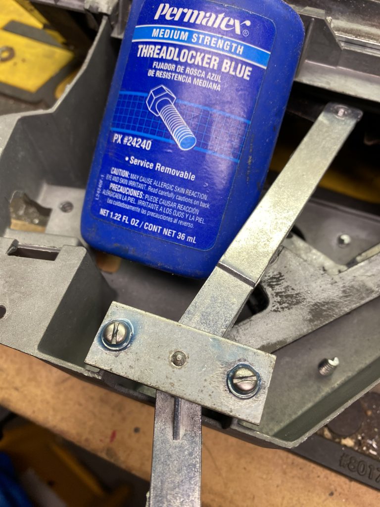
Once past that hurdle it was a matter of putting the screws in with some locktite and reassembling it.
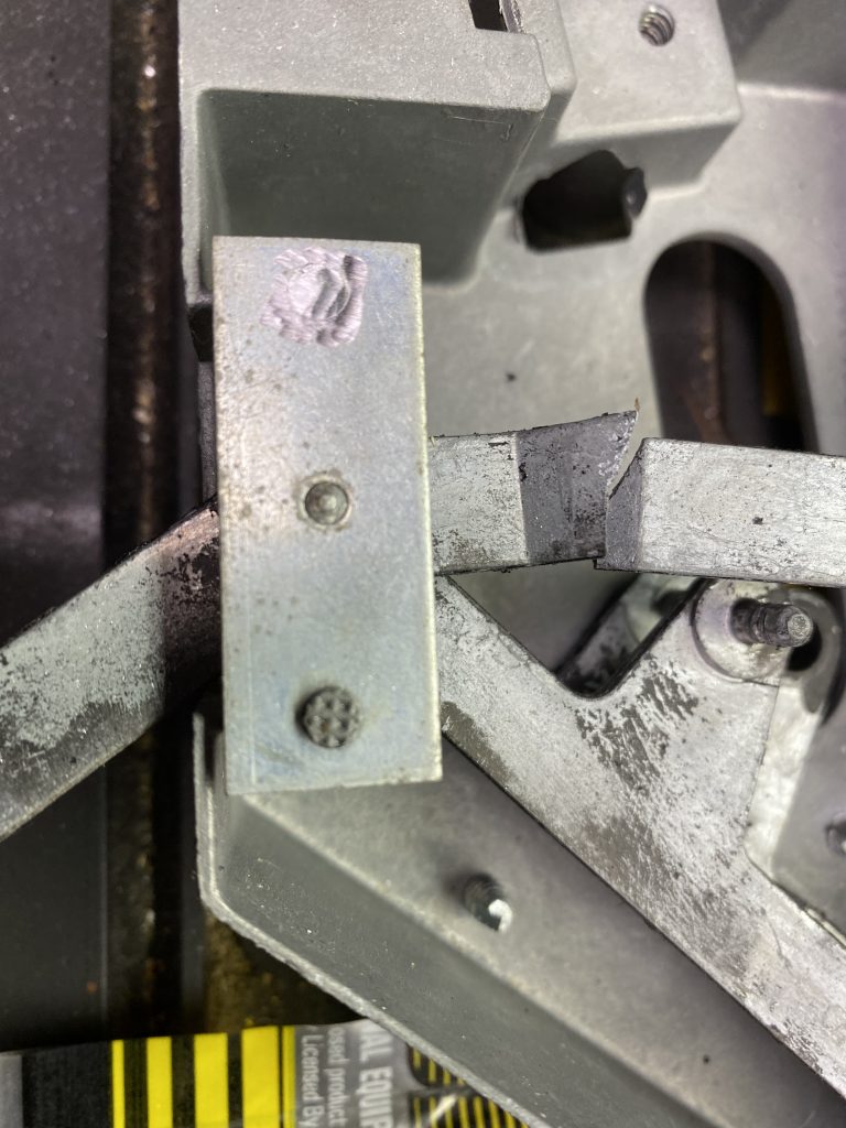
The hole in the end of the new lever also needed to be tapped so it can be reconnected with a screw.
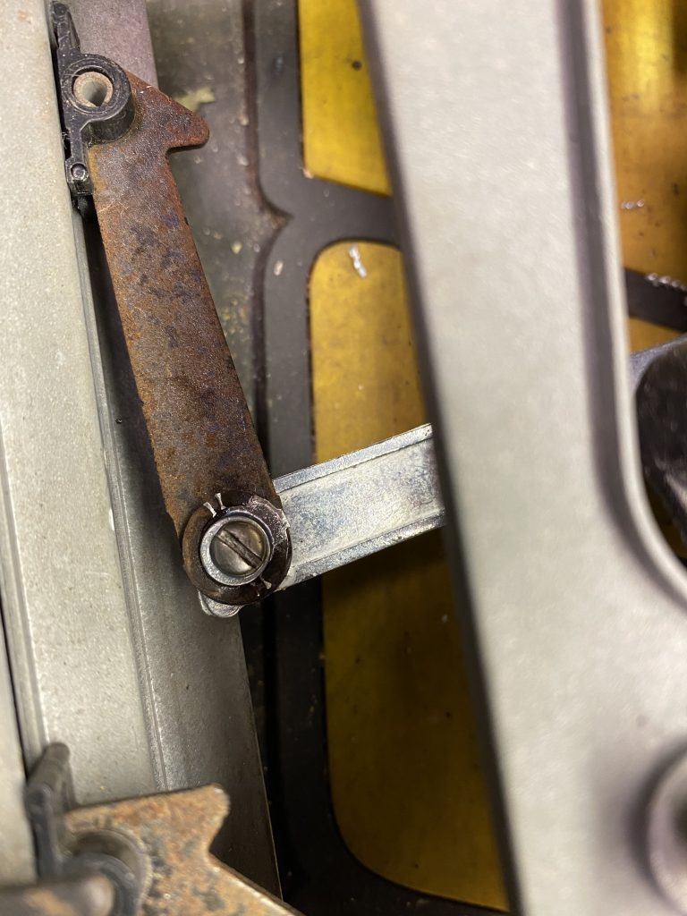
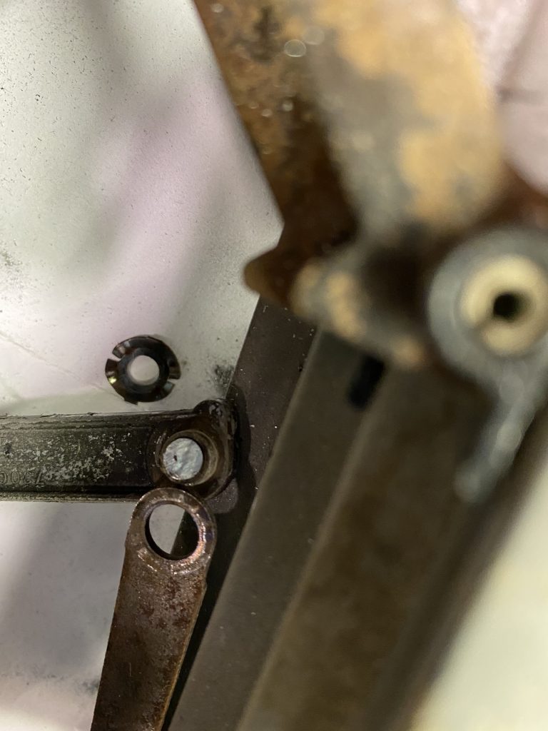
Back together again…mostly. Each cable has a loop on the end that fits on a peg on one of the levers. The loop is supposed to be secured by a push nut, which looks like a washer with cuts radiating from the center hole that grip the peg.
I managed to lose or break all of the original three push nuts, plus a fourth one that came with the repair kit. Someday I’ll buy some and install them, but it looks like it will work for now. Tip: buy extras when you buy your kit.
This does actually work, and the defroster diverter valve does open and close as you slide the defrost lever, but…it’s a fix that doesn’t really show up well in pictures. Looks about the same as when I started!
My father had a 68 Firebird when I was growing up. (The dash is virtually identical to a 68 Camaro.) At some point, the defroster lever broke, like pretty much all of them do eventually. I remember hitting a local junkyard and pulling a replacement climate control panel from a car there, and swapping it in. Unsurprisingly, a few years later, the defrost lever in the replacement one broke also. I took it apart and drilled a series of holes along the side of the crack and sewed it back together with some wire, and slathered the whole thing with epoxy. That lasted another few years before it broke again.
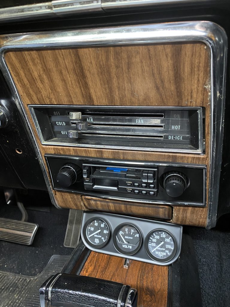
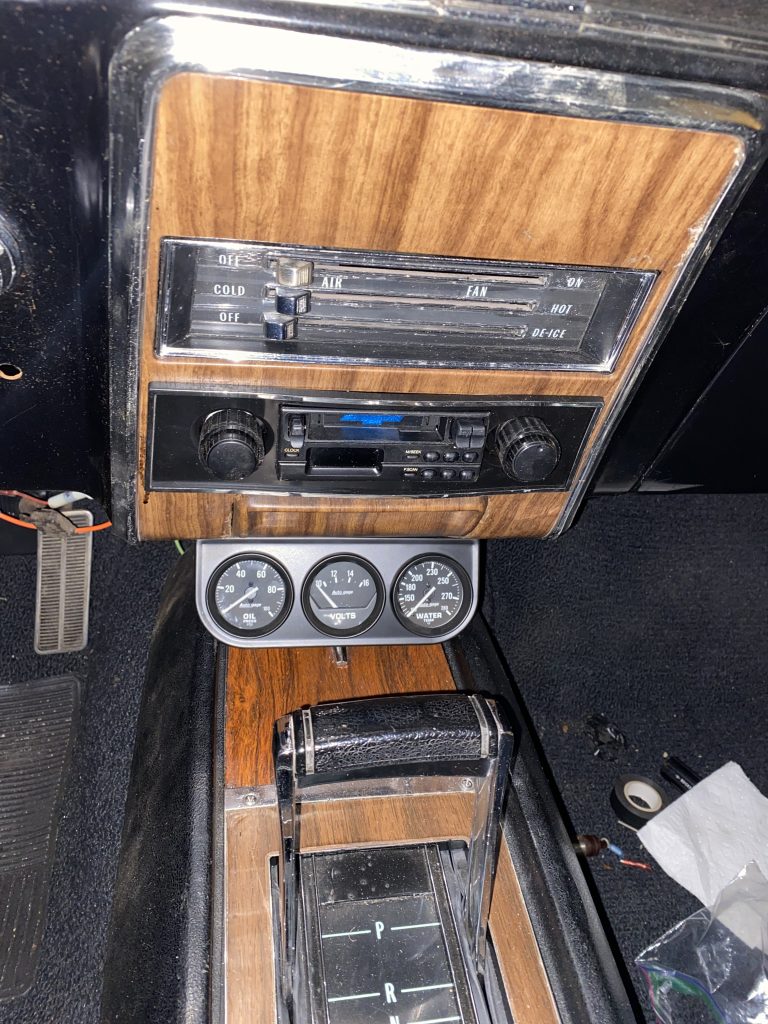
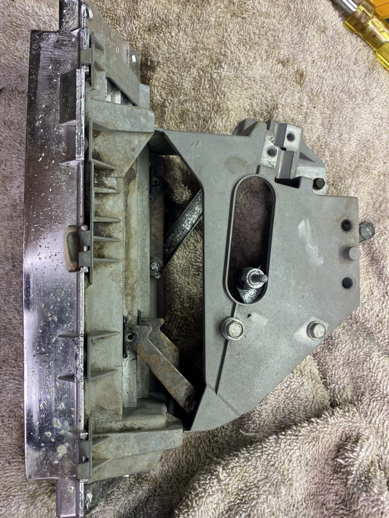
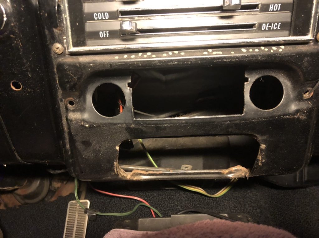
Fast forward to today, and…the defrost lever in our Camaro is broken. As the control panel is at the top of the dash, everything below it has to come out to get enough room to remove it. The aftermarket gauges, the ashtray, the radio, and the front woodgrain bezel all need to be removed.
I ordered a replacement lever (OEM brand) which is still cast metal, but it is definitely beefier than the original one.
After removing the control panel, it was a bit ripe on the top side where the mice had used it for part of their travels.
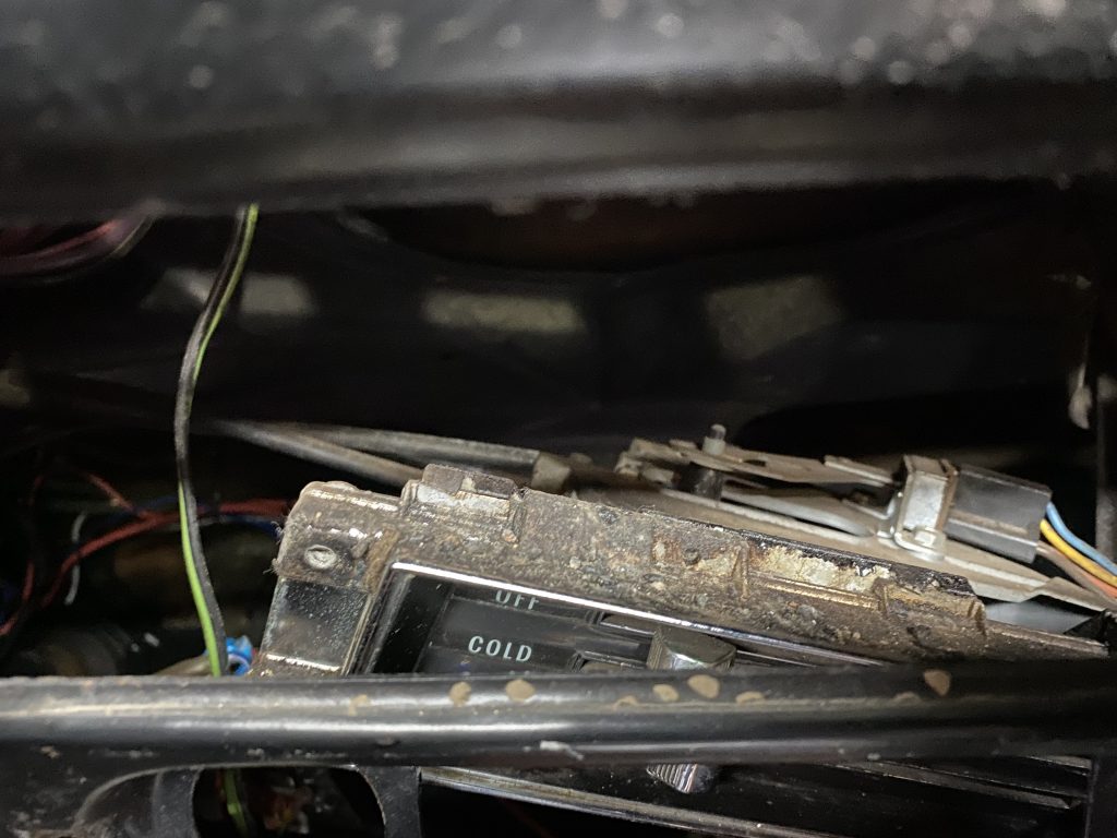
I didn’t figure it out at the time, but if you unplug the blower fan wiring (the plug at the right of the picture above) and pull the light socket out from the RH side, the whole unit can swing down between the dash and the gas pedal with the cables still attached.
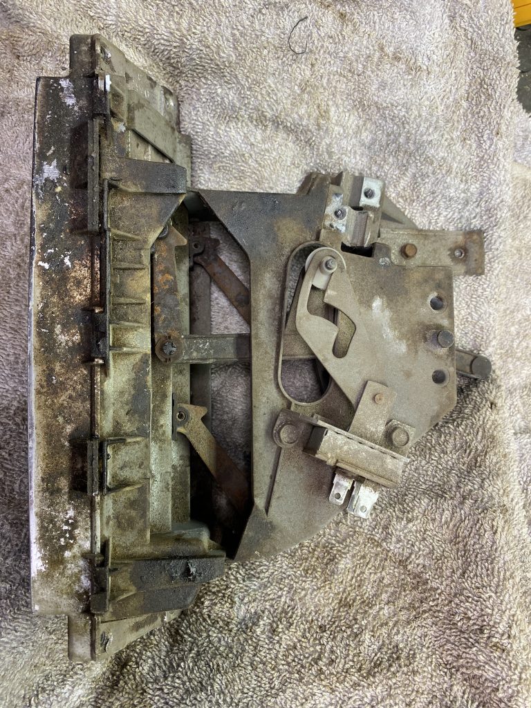
I decided the first step was to give it a bath in the ultrasonic cleaner.
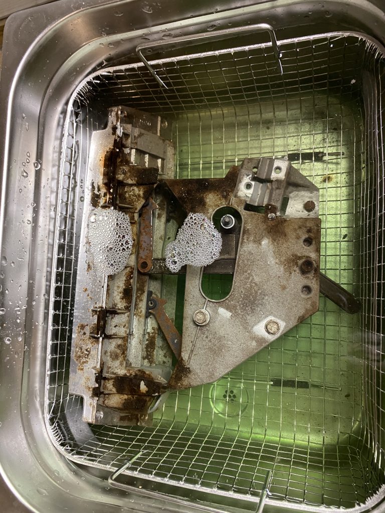
After a few cycles through the cleaner and a little scrubbing with a nylon bristle brush, it came out looking better.
Next step is removing the old lever. Stay tuned…
I don’t know why exactly, but the astro-ventilation assemblies always fascinated me. They really seem like an important part of the dash design, and not just an afterthought.
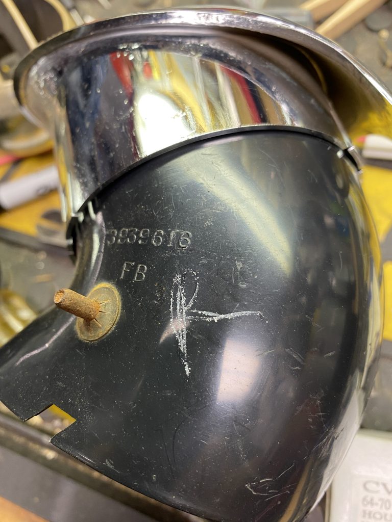
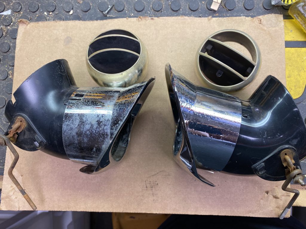
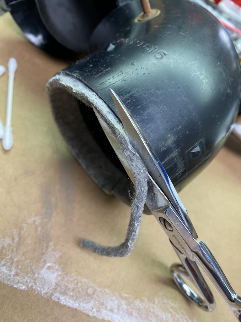
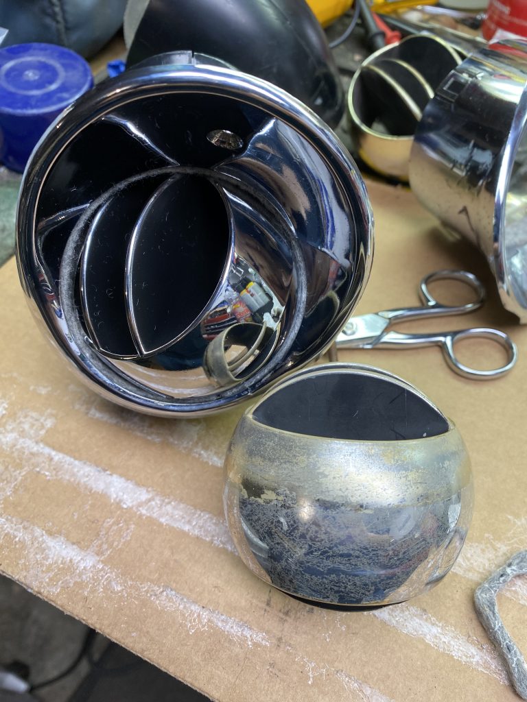
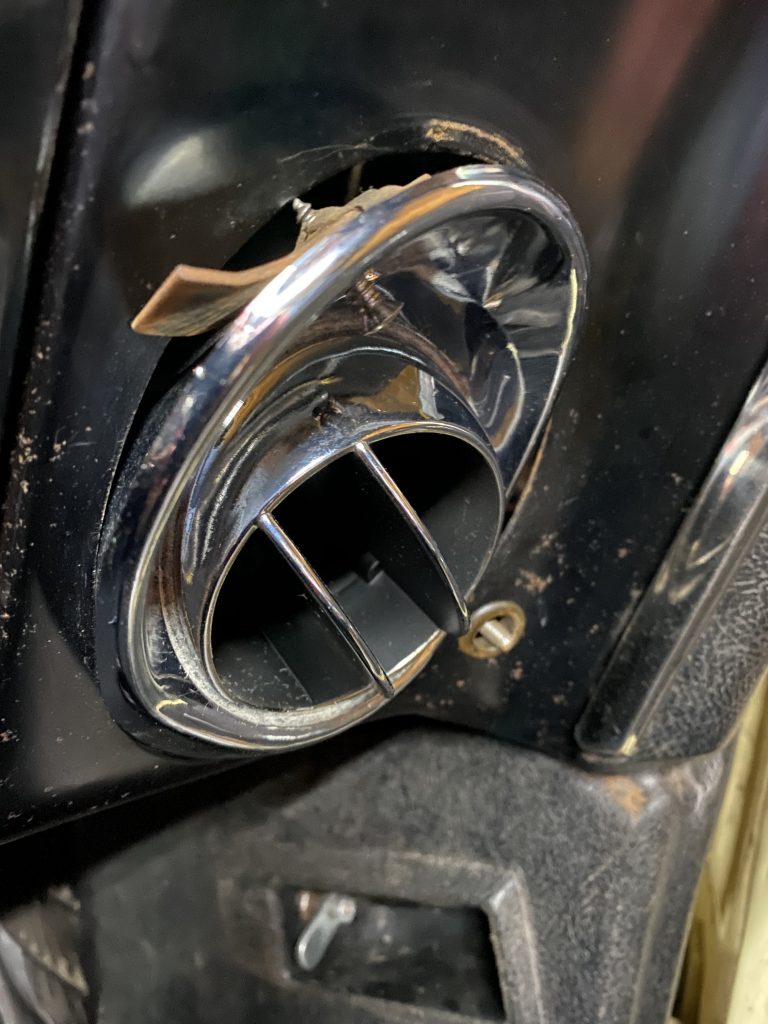
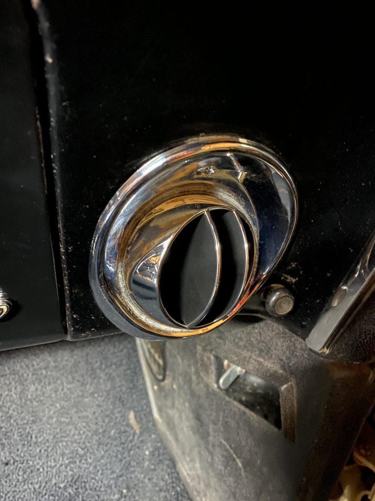
The ones in the car had seen better days, they look like they are original pieces. The housing was in very good shape, the chrome on the bezel was all intact and smooth, but the felt seals had turned to dust a long time ago. The chrome on the ball parts was in pretty bad shape, probably about half of it had worn off entirely. I purchased new aftermarket balls, and a felt seal kit. The new pieces were not exactly like the old ones. Most notably, the new ones had a distinct separation line around them, while the originals were all smooth.
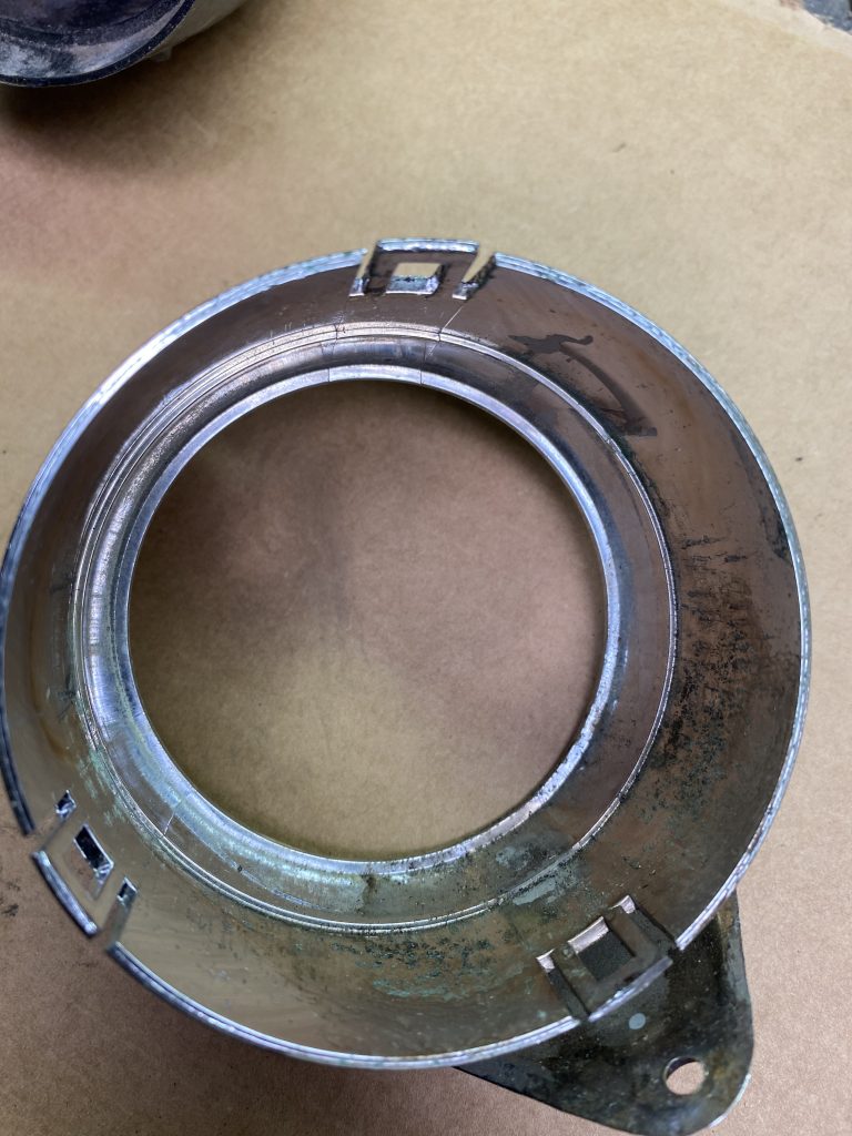
The first step is disassembling and removing the housings. There are two screws on the bezel, one at 12 o’clock, and another one at 6. The bottom screw goes directly into the dash metal, but the top one goes into a short curved metal bracket that pinches against the back of the dashboard. You don’t technically need to take the top screw out all the way, just loosen it up a lot until the bracket is loose. If you take the screw all the way out, make sure you don’t lose track of the bracket. The two screws are different length, the short one goes on the bottom, and the longer one goes in the top hole.
The control knob next to the housing unscrews, leaving a threaded rod. This is the same as the door lock knob if you need to replace it.
The natural thing to do is to pull the housing out of the dash, but that leaves the threaded rod stuck in its hole in the dash, which doesn’t allow it to come out. The trick is to pull it out just far enough that you can get the bottom of the housing to push back through the dash opening. Once it’s there, turn the housing 90*, which will pull the threaded rod out of its hole, then you can feed the whole assembly out through the front.
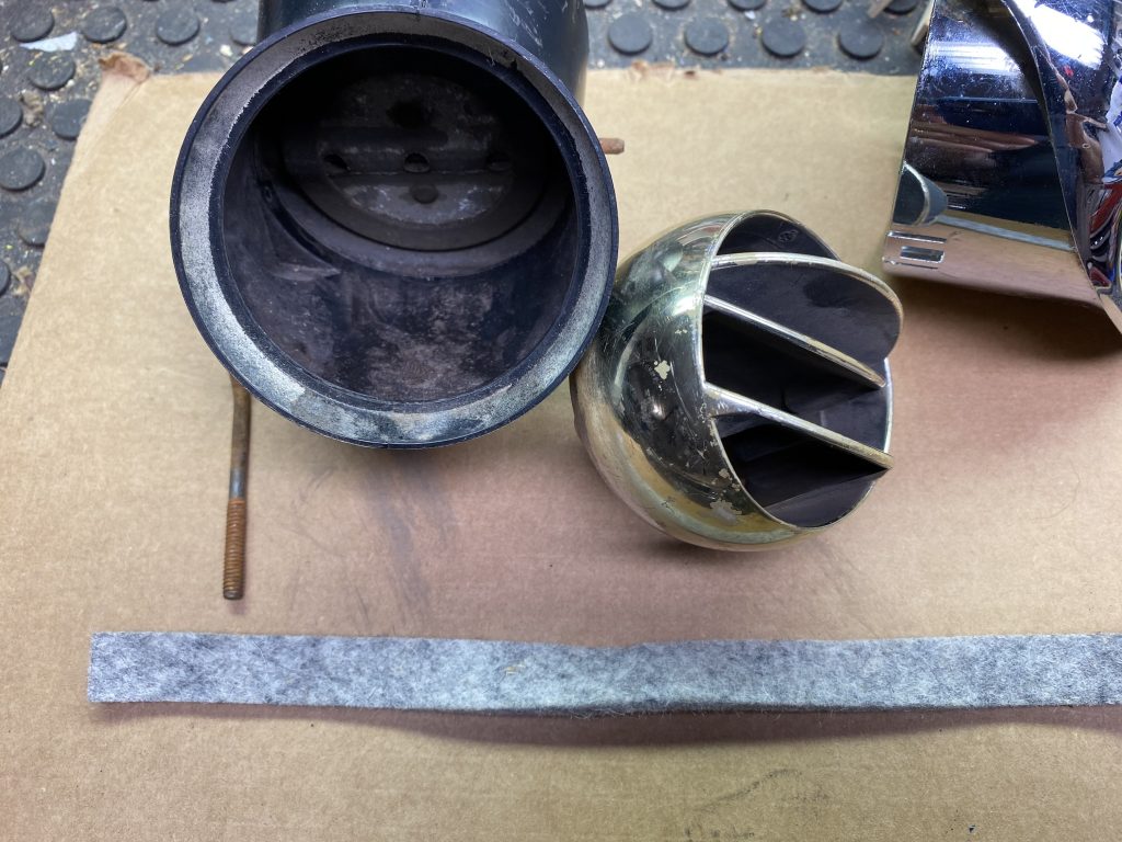
There is a short plastic oval flexible tube that connects the back of the assembly to the cowl vent. This may fall out as you take the vent assembly out, as there’s no fasteners on it, it’s just held in place by the vent assembly.
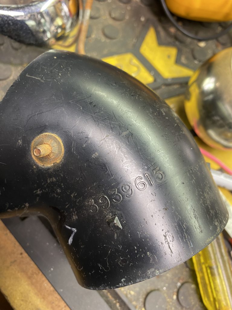
Once the assemblies are out, mark them left and right so you don’t get them mixed up. You can identify which goes on what side by the threaded rod lever is on. 3939616 is the RH one, 3939615 is the LH one.
There are three tabs on the chrome bezel that fit over corresponding bumps on the black plastic back half. To disassemble these, you need to carefully separate the two halves, and gently pry up on the tabs to get them past the bumps.
In my case, the flapper valve was in great shape, and did not need any repair. You may need to disassemble this part and add new rubber seals.
I used Permatex upholstery adhesive to attach the new felt pieces. This is the same glue I used on the headliner. It’s contact cement, which means you put it on both pieces, let it dry a little while, then stick the pieces together. It’s very sticky, and you only get one shot at putting the parts together, as it’s very difficult to separate them.
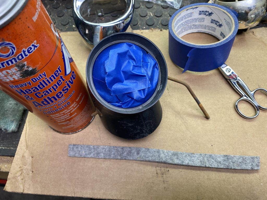
I sprayed the adhesive on the felt pieces, then sprayed a bunch of it into a baggie and used a q-tip to paint the adhesive on the housing surfaces. (Originally I had planned to spray the housing piece also, which explains the blue tape. I decided to try the q-tip, and that worked out much better. No tape required.) After 5 minutes I gave everything a second coat (per label instructions) and let it sit for about 10 minutes.
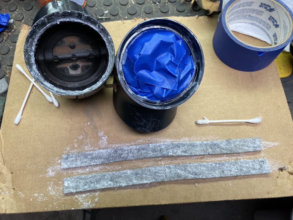
Once the glue had set up and was tacky, I carefully worked the felt strips around the housing mount surface, and trimmed off the excess when I got back to the start again.
I let this sit and dry for a day (per label instructions) before doing the final assembly.
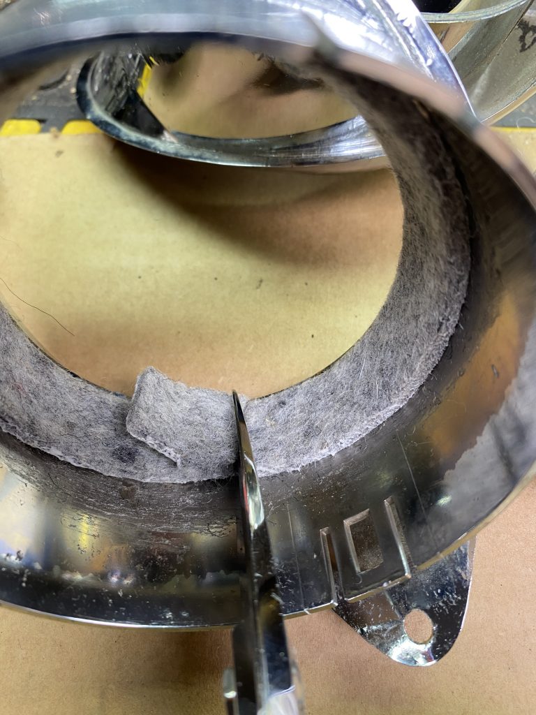
On the black half of the housing, I used scissors to trim the felt flush with the edge of the plastic. On the chrome half, there wasn’t a good way to trim off the excess, so I just left it. It might be a good idea to trim these to the correct width before gluing them on, but it seemed to work with only the other half trimmed, so…maybe that’s not necessary.
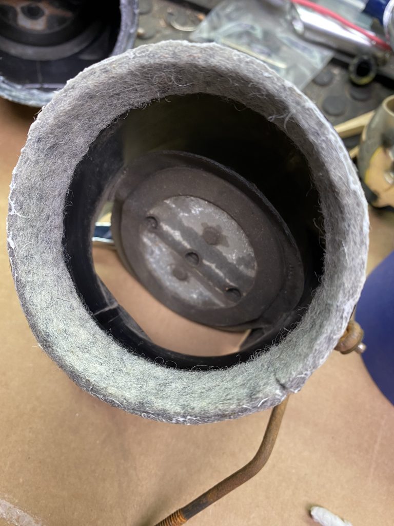
Reassembling the housing is straightforward, put the ball in, and carefully press the two halves together until the tabs engage the bumps. Make sure everything works smoothly before continuing.
Putting the housings back in the dash is the toughest part of the job.
Good news: I think I have a promising second career as a contortionist.
For the driver’s side, there’s zero room to get your hand up there with the parking brake assembly in place. It can be done without removing the parking brake! The surprisingly successful installation approach was to turn it 90* and feed the assembly from the front all the way through the opening so the bottom of the bezel was completely behind the dash, then rotate it upright again and tip the top edge back out through the opening while feeding the threaded rod through the ferrule.
The same process works on the other side. In this picture, the bottom edge of the housing is inside the dash, the top edge is out, and the threaded rod has been fed through its hole.
Continue pulling the assembly out until the bottom edge comes out. The oval flex tube joint goes on next, then align and tighten the screws. For the top screw, thread it through the bezel and into the metal clip, but leave it loose. Once you get it into place, use the screw to rotate the clip until it’s facing the right way (longer curved end up), then pull down on the bezel to pinch the clip in place while you tighten the screw.
It took me 21 months to go from this:
To this:
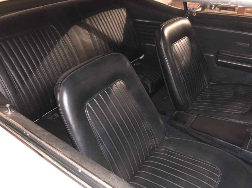
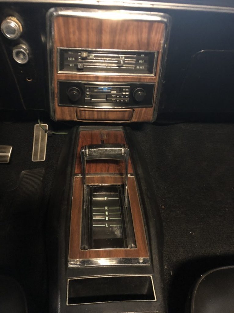
I managed to get the console installed finally…
There was a bit of last minute drama when the dashboard ashtray did not fit correctly, and the screws for the bracket are much much MUCH easier to get to with the console out, so I decided to spent a little time on that.
Somehow the previous owner had managed to screw up the opening so it was rounded on the sides. I am still puzzled about why this was done. I could believe the radio hole getting cut out to a larger rectangle, but that section of the dash is intact. Why (and how?) they rounded the sides of the ashtray opening I will never understand.
I took the face plate off of the dash, and poked at it a bit, enough to get the bracket to aim the ashtray low enough to actually seat into the opening.
I also did some caveman hammer-and-dolly work on the trim plate to get that sort of back into shape again. Someday I’ll get the ashtray fitting better and I’ll spring for a new trim plate, but it’s good enough for now.
I buttoned it all back up, and…it’s passable. I wasn’t planning on using the ashtray anyway.
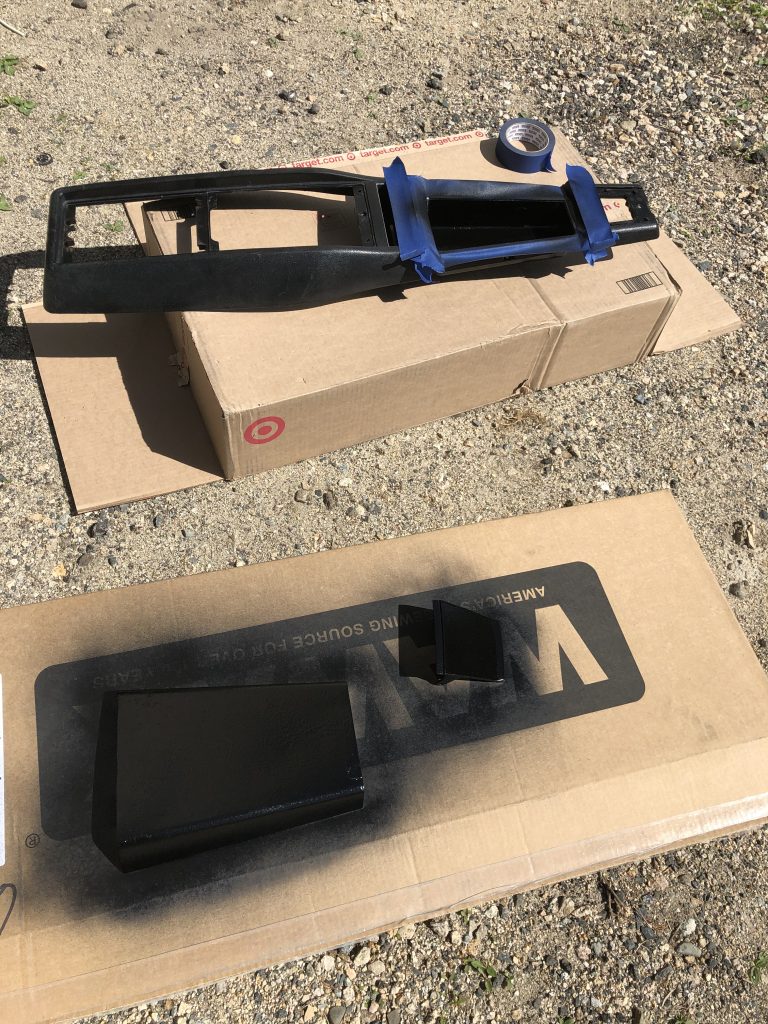
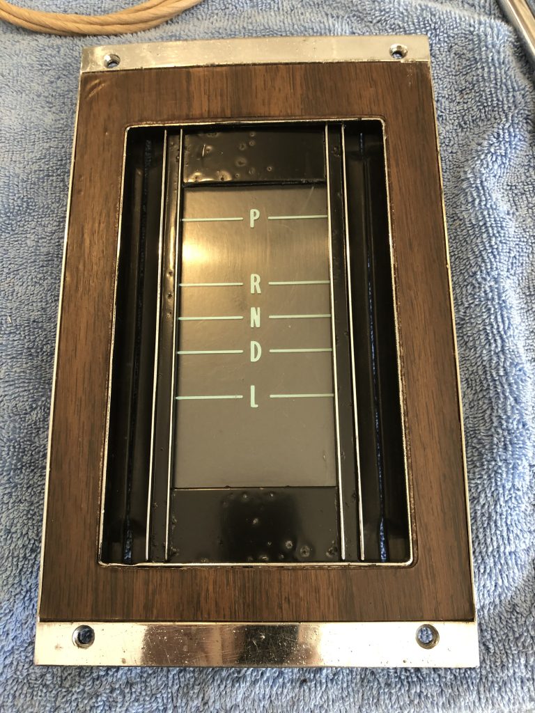
With that last hurdle out of the way, a little paint, new rubber gaskets on the shift plate, and…bolted into the car at last.
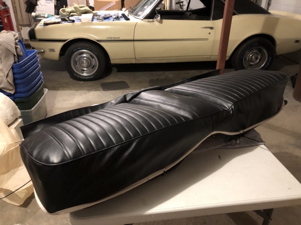
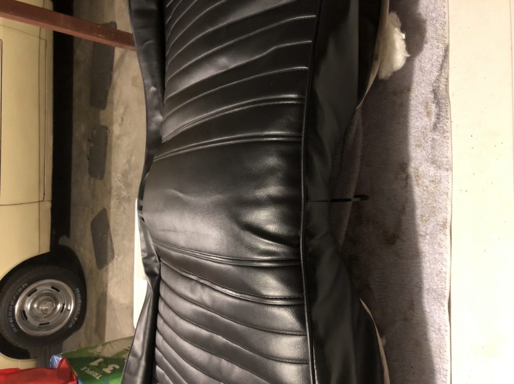
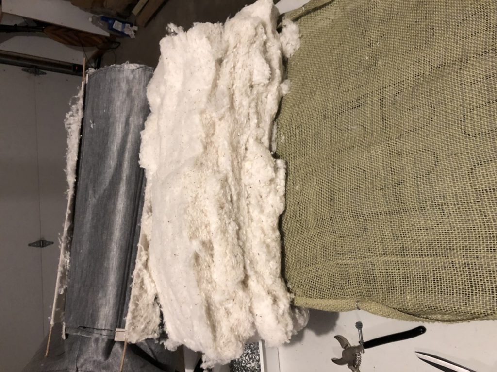
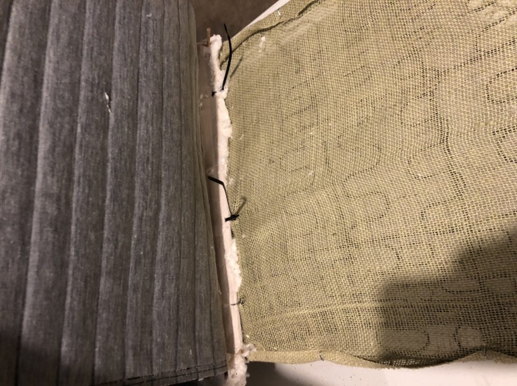
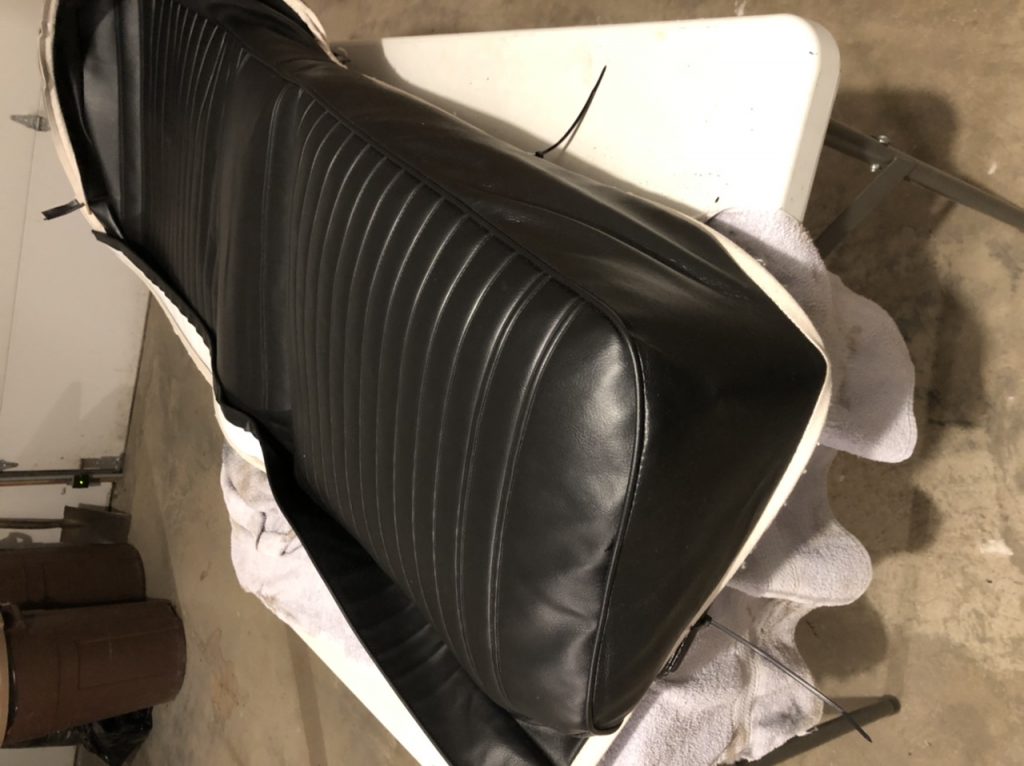
I got the seat base edges tacked down with zipties…and then decided I didn’t like the way it was fitting. Note the white shows on the edges on the front and sides. Too far back on the frame. So, I took it apart again.
The edges were not landing where they needed to, and it was crooked. Since the center section listing wire gets attached first, you can’t shift it afterwards.
I started over by ziptieing the middle of the listing wire to the center back attachment point of the frame. This is about 2” in from the back edge of the frame. That leaves enough room for the cover flap to wrap around the edge about even with the inner edge of the frame
From there, I Hinged the cover back and put batting in for the center section between the listing wires. I ziptied the center wires to the springs, then replaced them with hogrings.
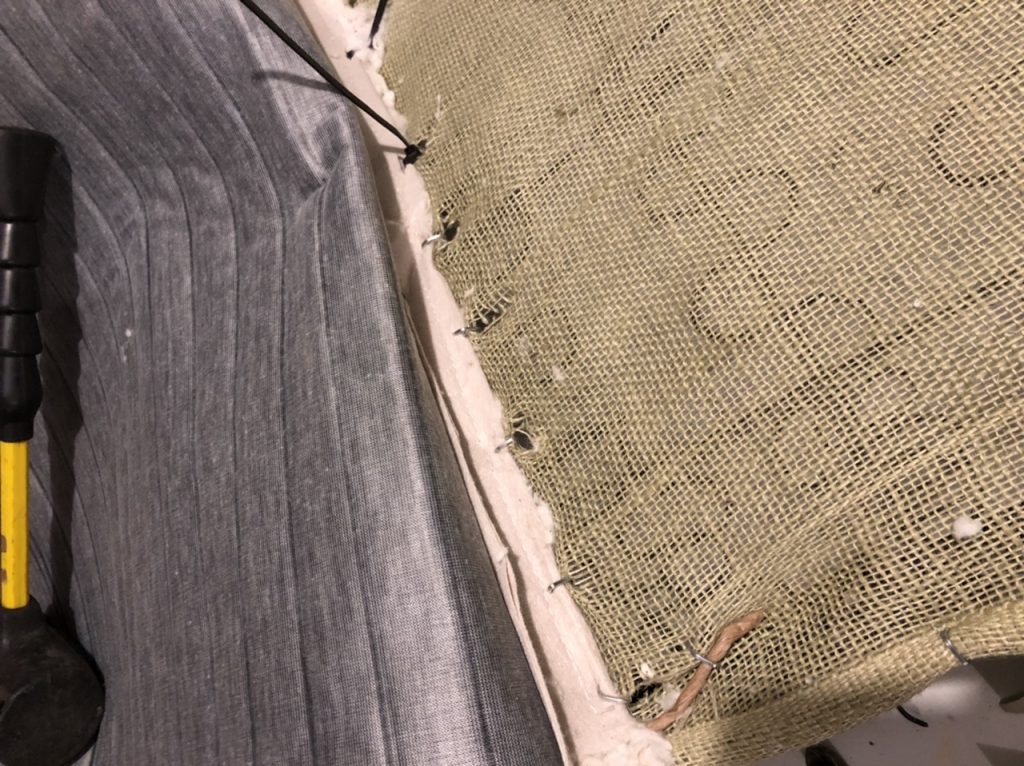
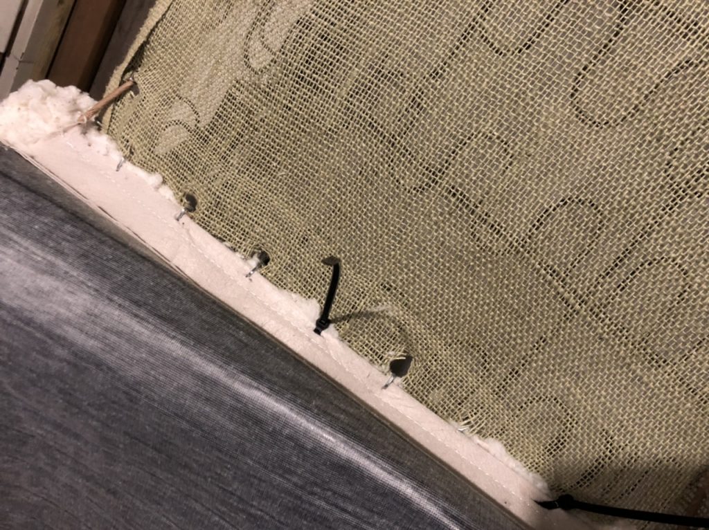
Then I moved on to filling each side section and attaching them with zipties.
…and then replaced the zipties with hogrings, and attached the rear edge flap on the cover around the rear edge of the frame.
 and then the moment of truth…
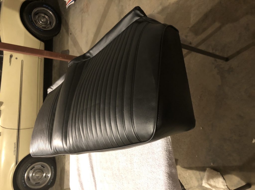
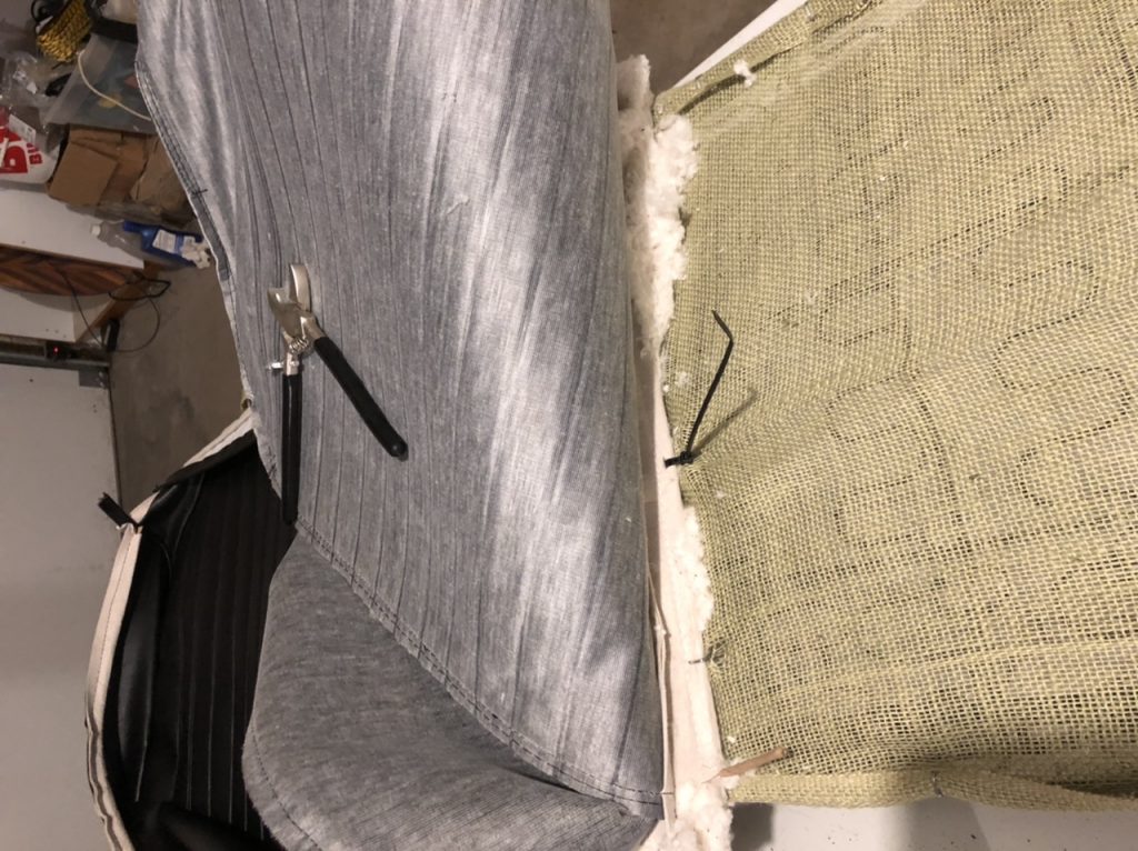
The seat bottom looks fine, but the seat back looks terrible. It’s showing the white backing, and it looks wrinkled. I’m taking it out again to redo that soon.
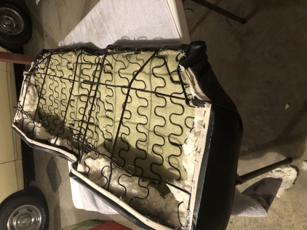
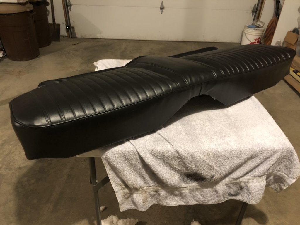
Almost done… I got the seat base mostly done tonight. I have to do the final batting adjustments and hog ring the outer edges down, but it’s looking like a seat again. Good progress for the evening.
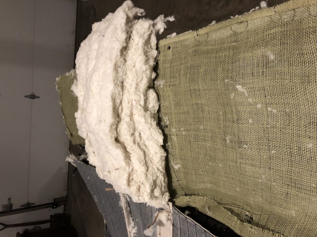
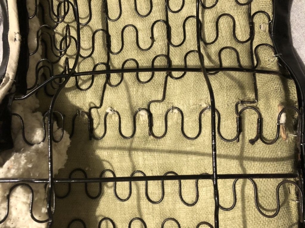
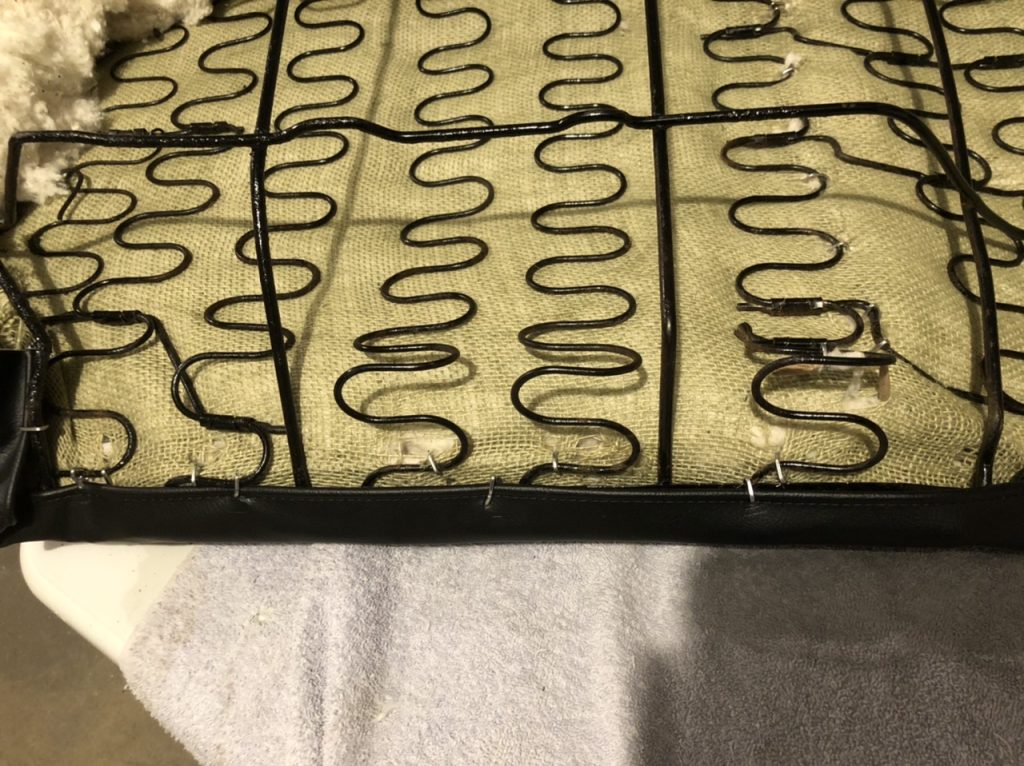
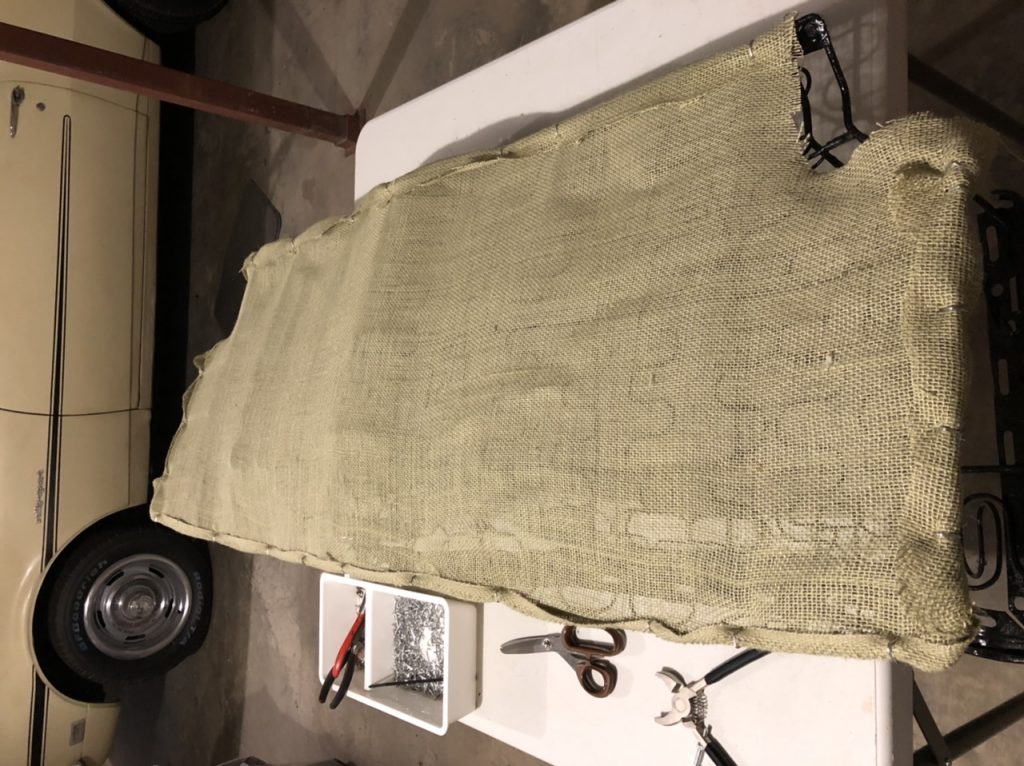
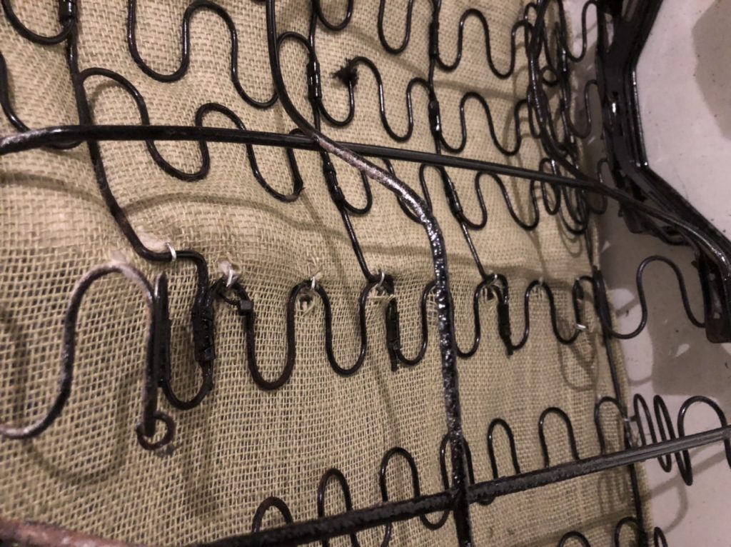
I started by attaching the burlap base and attached it around the edges.
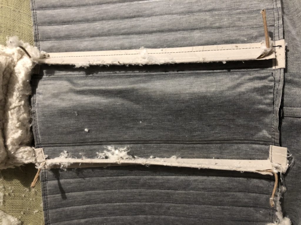
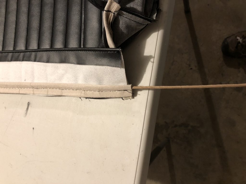
next was inserting the new listing wire into the sleeves on the cover
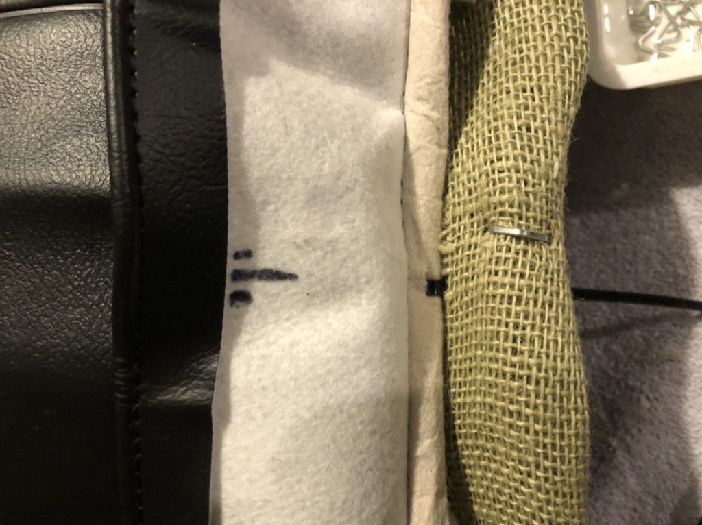
for the sleeves on either side of the driveshaft hump I had to clip the ends free just inside the topstitching. I’m not sure why they are assembled this way, but it seemed like the right thing to do.
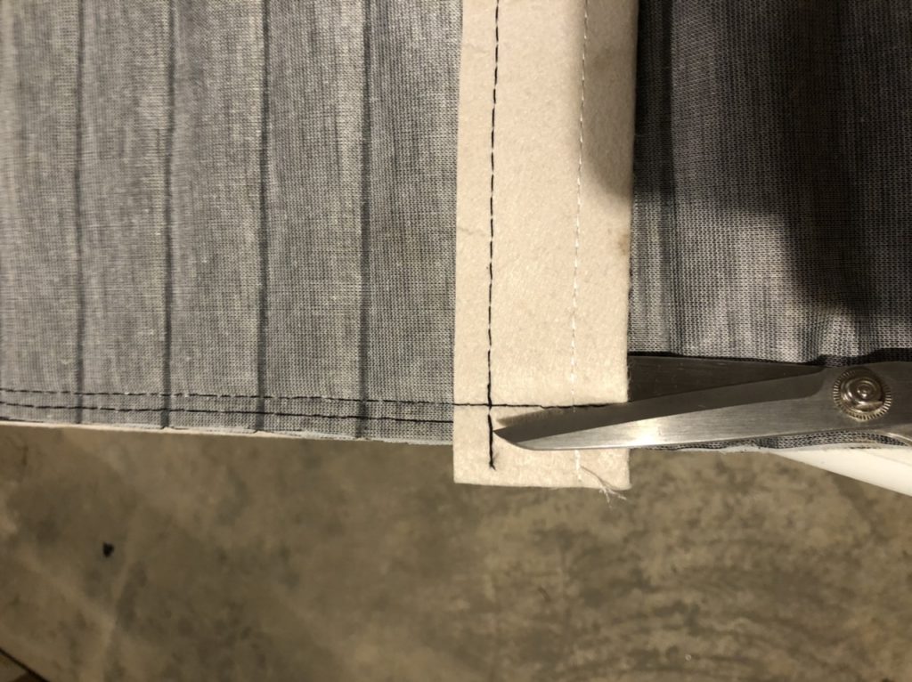
I cut these long because the original ones were done that way with a bend at the ends.
the longest piece goes from the back corner, across the front, finishing at the other back corner.
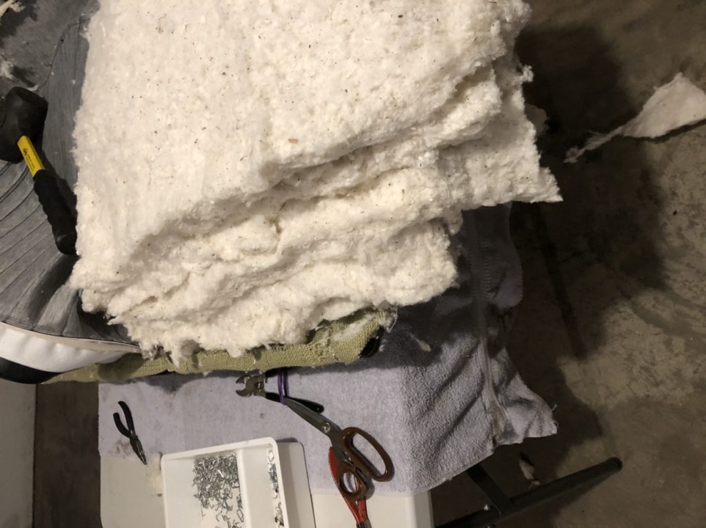
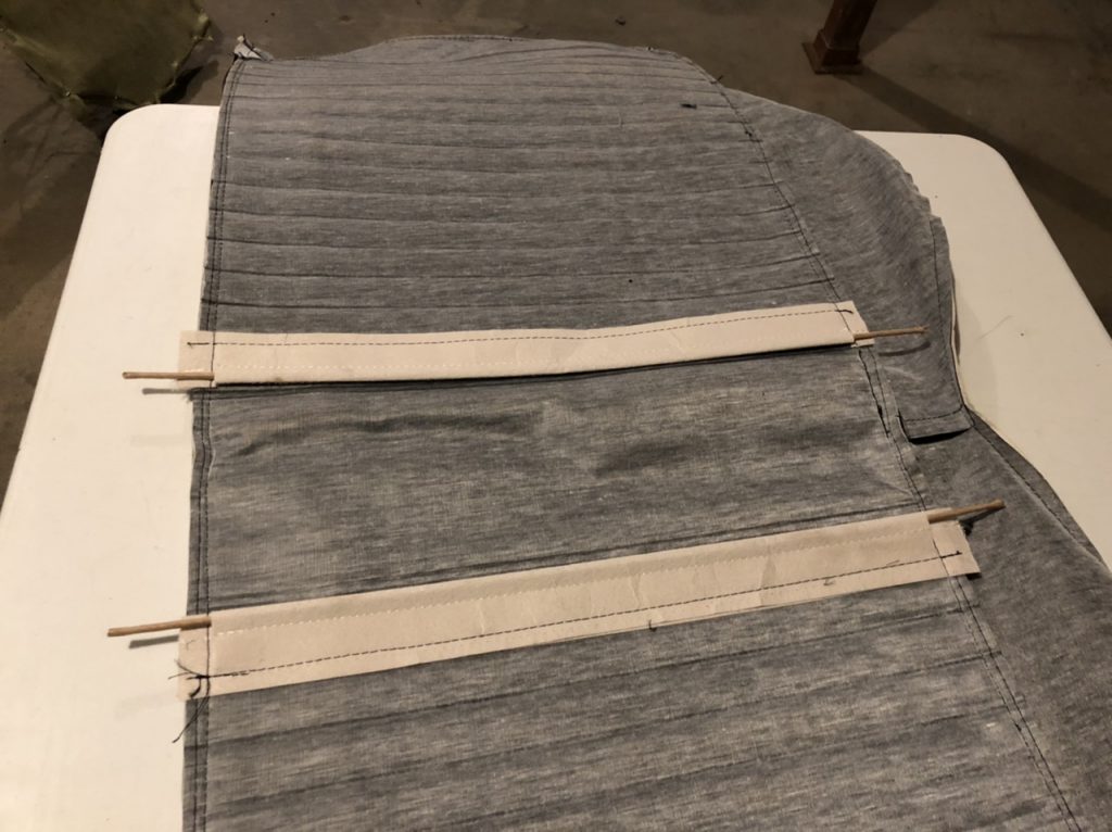
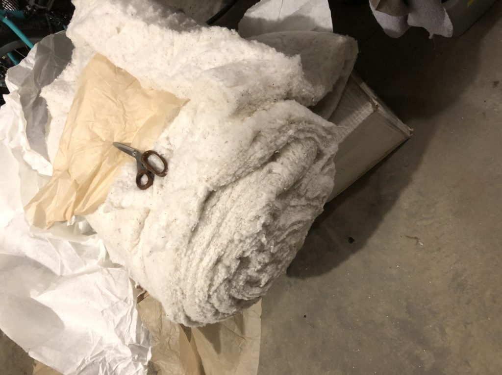
I worked on the center section first. It’s a bit of a guess at how much batting to use but the original wasn’t padded as much here, and it has to fit underneath the seat back. It’s also tougher to go back and redo this so I tried hard to get it right the first time. It’s also tough to get the hof rings in olace, so the ziptie trick helps a lot here.
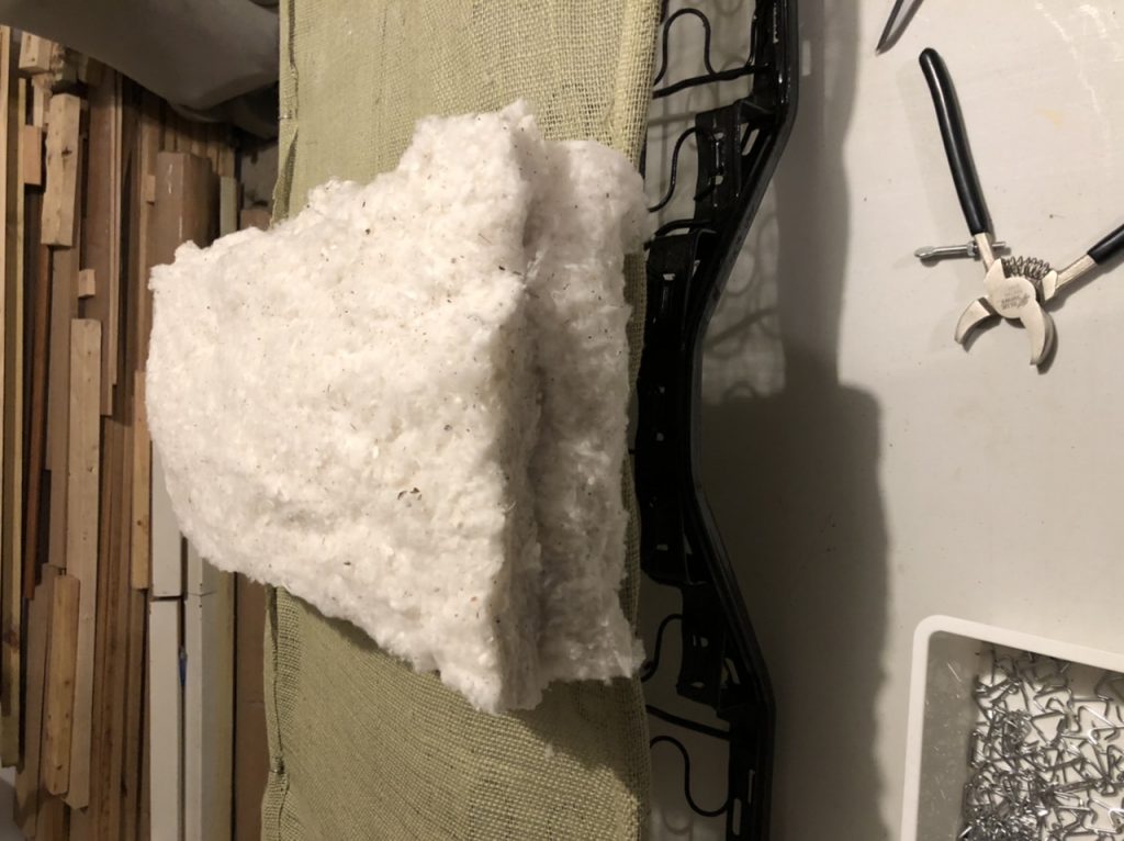
once it was snugged down, i added hog rings at each speing loop
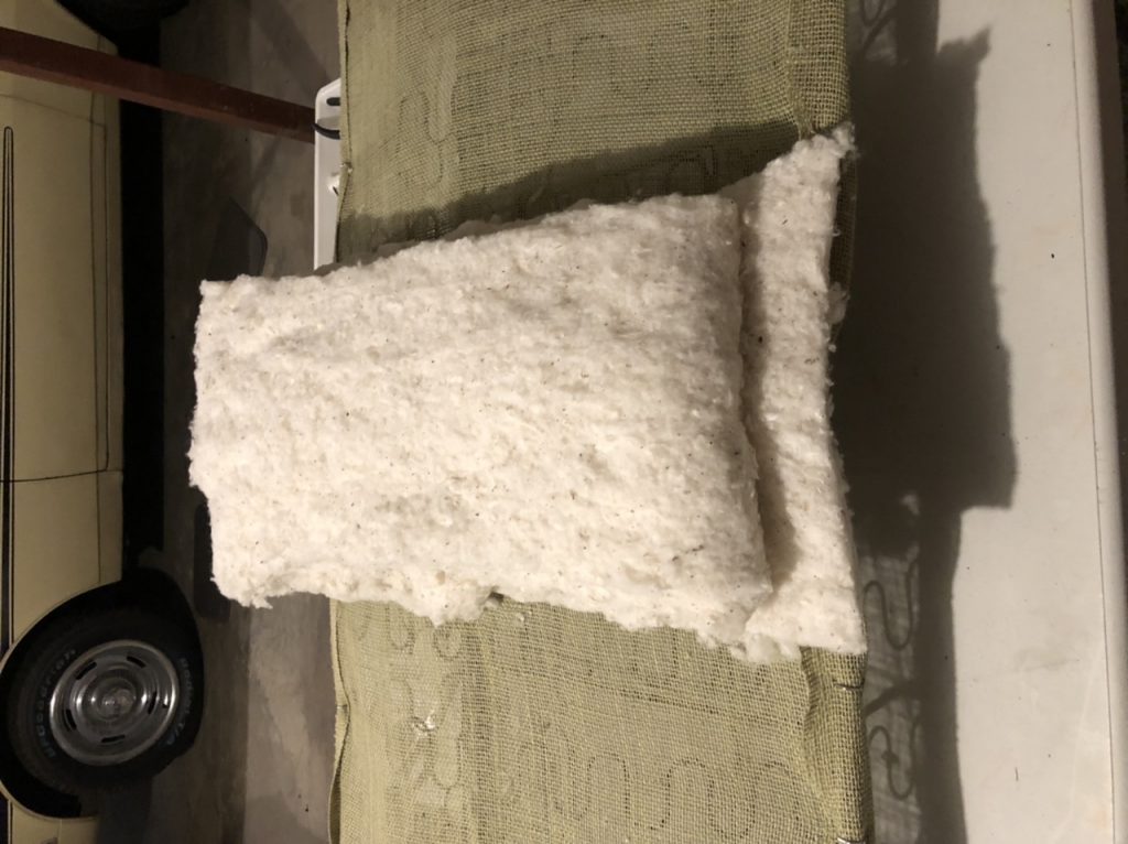
Next was the sections between the center and the side. I kept guessing at the right amount of batting. I adjusted it a few times and snugged the cover into place with zipties each time.
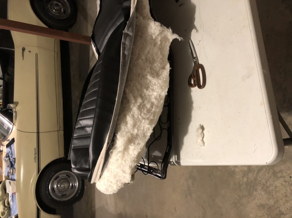
 and once more for the other side
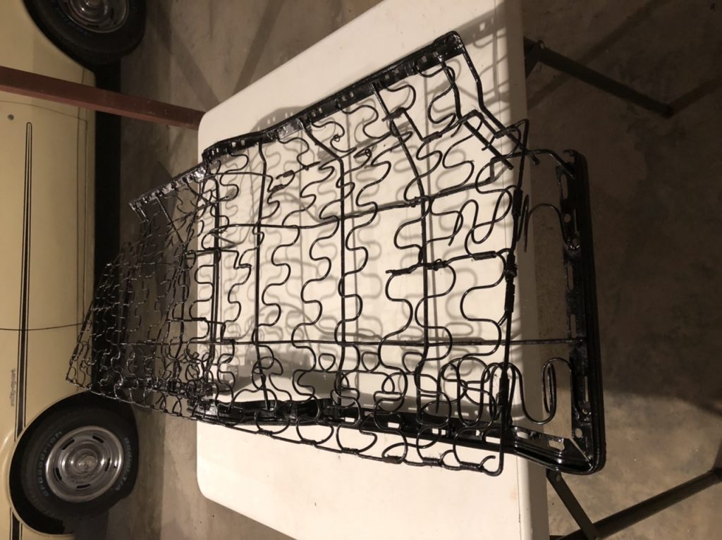
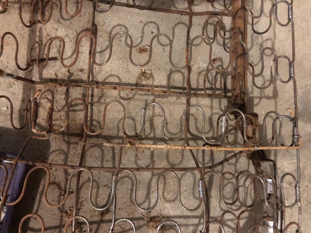
A little progress, I finished stripping the springs and got them painted. Again, it’s not really necessary to paint it, but it’s nicer to work on something that is clean.
There is listing wire across the back, as well as on either side of the driveshaft hump. Last pictures of the old stuff before I took it off:
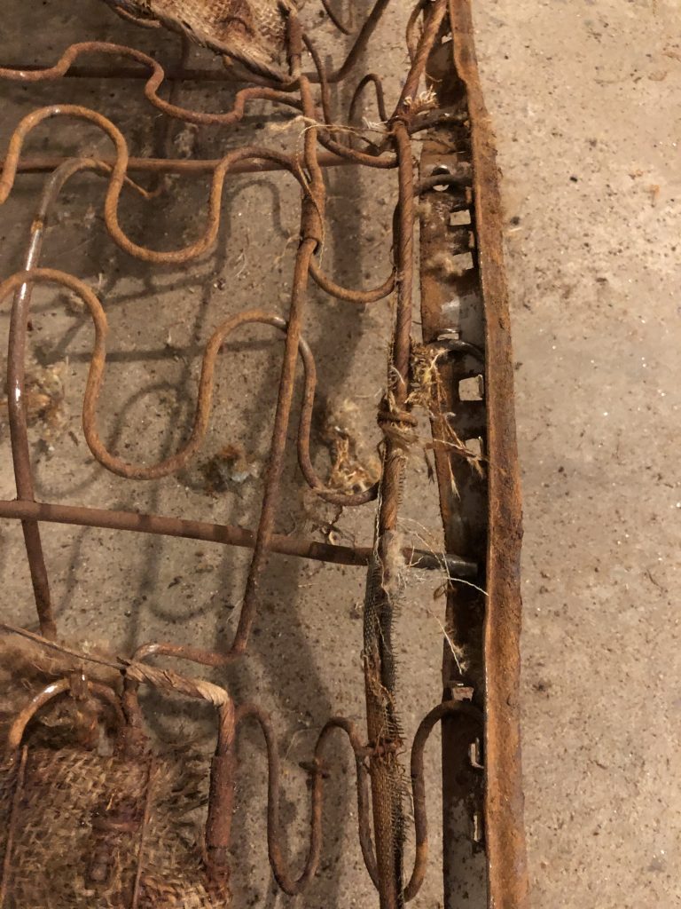
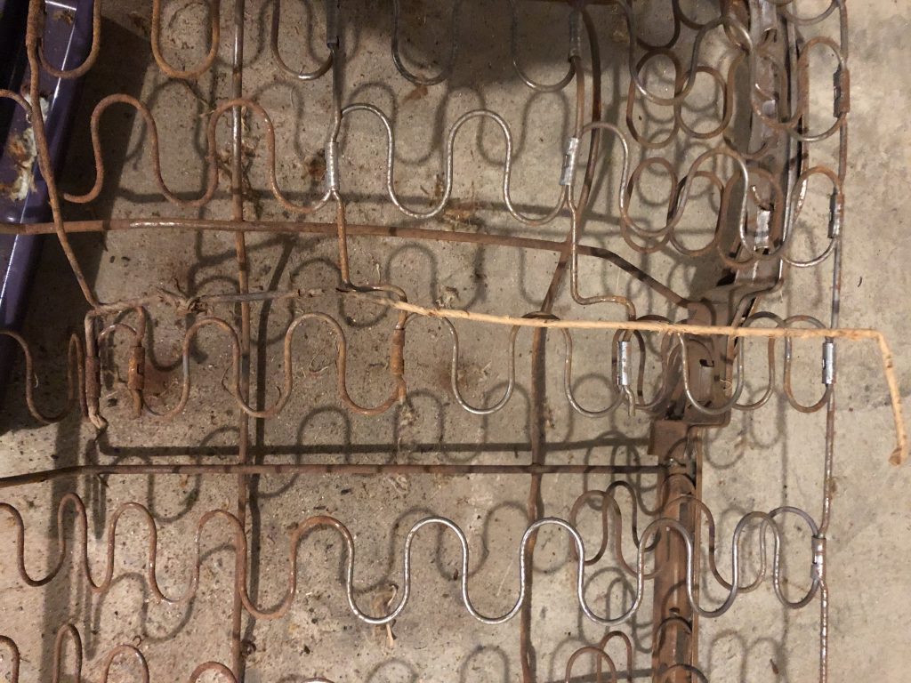
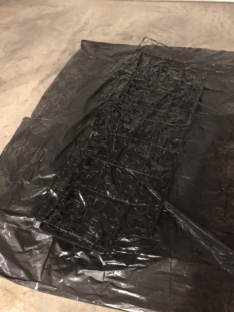
A bit of wire brush work and time for paint:
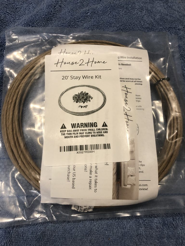
The listing wire arrived in the mail, time to put it all back together again