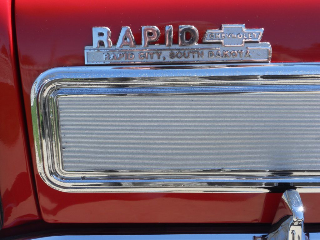
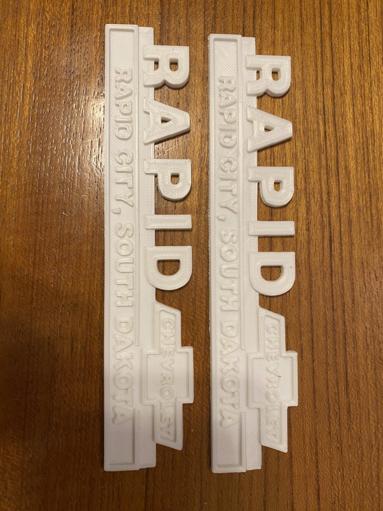
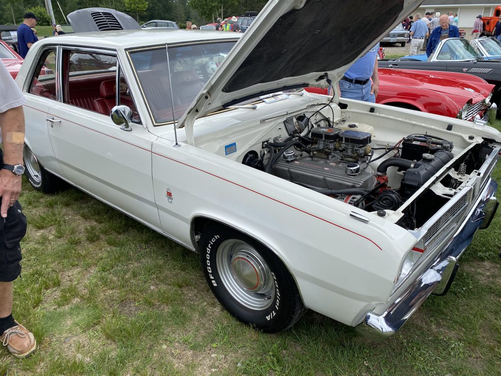
Someone on the Nova board was looking for a dealer emblem for their car. here’s a 3D printed version I made for them:
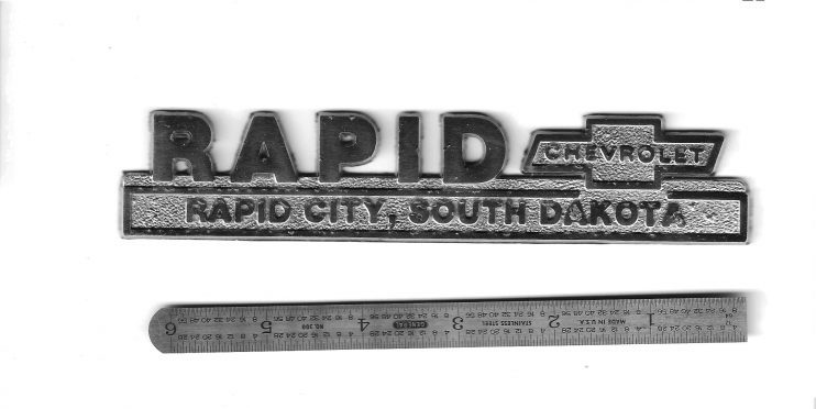
Original emblemScanned image of emblem
Using the scanned image of the emblem, I used GIMP to reduce it to a pure black-and-white image using the posterizing filter. Once that was done, I hand-edited the result to clean up and straighten the noise in the image.
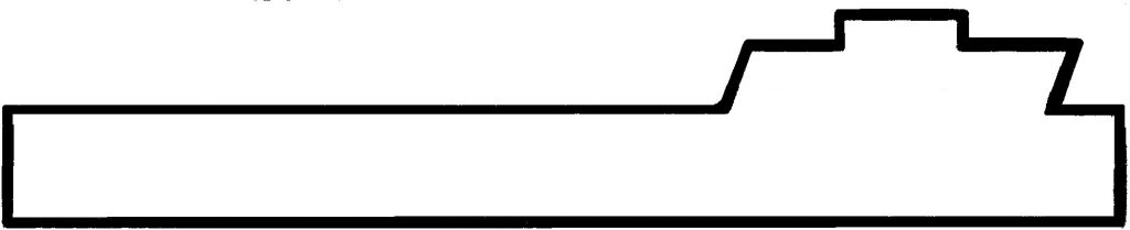
Foreground outline
Once the basic image was created, I used parts of it to make a background outline.
Background outline
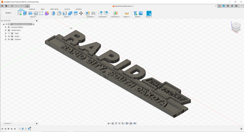
These two pieces were traced into SVG files using Inkscape to turn them into outlines. The SVG files were then imported into Fusion360, where I filled and extruded them to form the final object.
Background and foreground extruded in Fusion360
The object was saved as a STL file, loaded into Cura, and sliced for my Ender3 printer. I used PLA filament to print it.
3D printer in actionFinal result in PLA plastic filament
It’s not perfect, but it’s a good 10-footer if it is painted with chrome paint. Another option would be using a service like https://shapeways.com to render it in metal, or https://www.gcartrim.com/ to have the plastic plated.
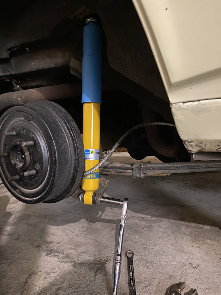
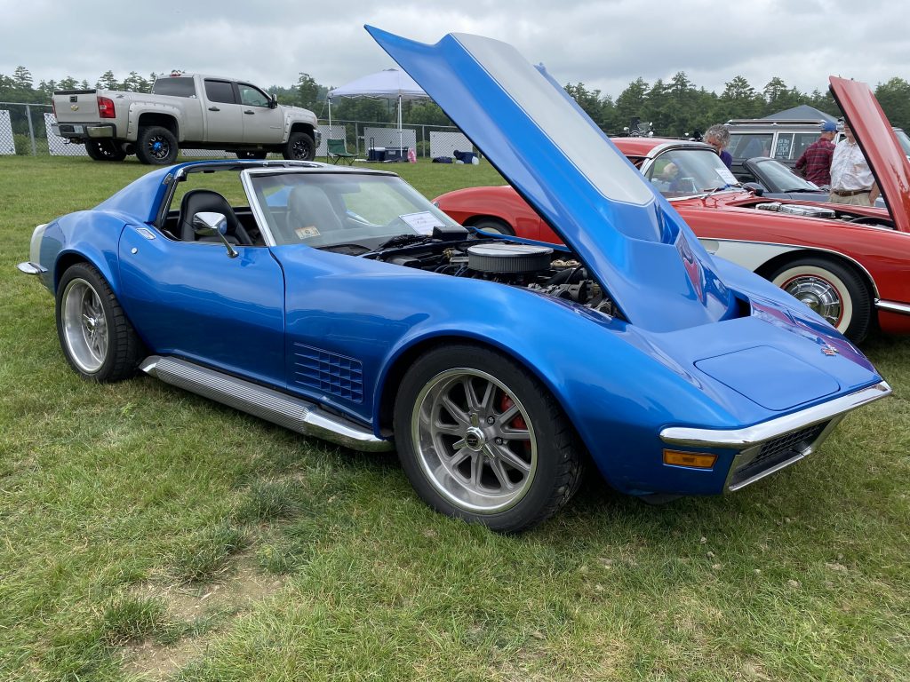
I’ve been driving the car more this summer since I’ve addressed a lot of the problem areas. The next item on the punchlist was getting it to ride more comfortably. The suspension felt very stiff, particularly in the rear, and going over potholes or train tracks felt like the car was going to shake apart. kaBLAM!
I didn’t want to change the ride height, so that actually limited my choices. Most of the springs/spindles/shocks available are for 2″ drop, not stock height.
After asking on camaros.net, I bought a pair of Bilstein AK2073 rear shocks. That was not the right part to order it turns out. It’s not clear on the Bilstein website, but AK2073 is for monoleaf applications, while AK2074 is for multileaf. The difference is that the multileaf has a taller spring pocket under the differential to accommodate the multileaf spring. That puts the shock mounting plate under the spring lower, so the shock needs to be a little longer.
But first…
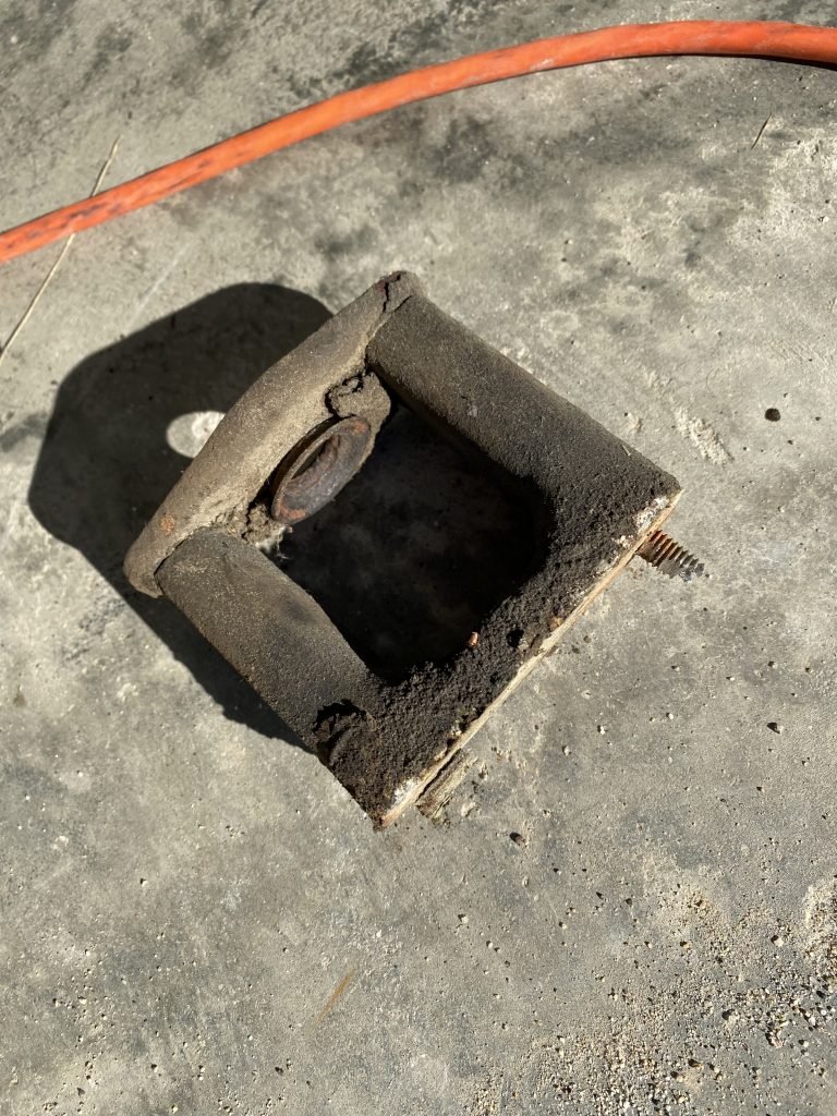
Way back when I first got the car and was redoing the brakes, I noticed that the right rear shock upper bracket was broken, so I decided to fix that. The setup was not stock, there was a mount point extender that was bolted to the upper shock mount, and the shock was mounted to that. The extender is commonly used to adapt the shorter monoleaf shocks to a car with multileaf springs. Moving the upper shock mount position lower meant the shorter shocks would work with the lower multileaf shock mount.
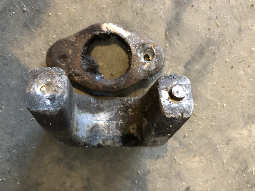
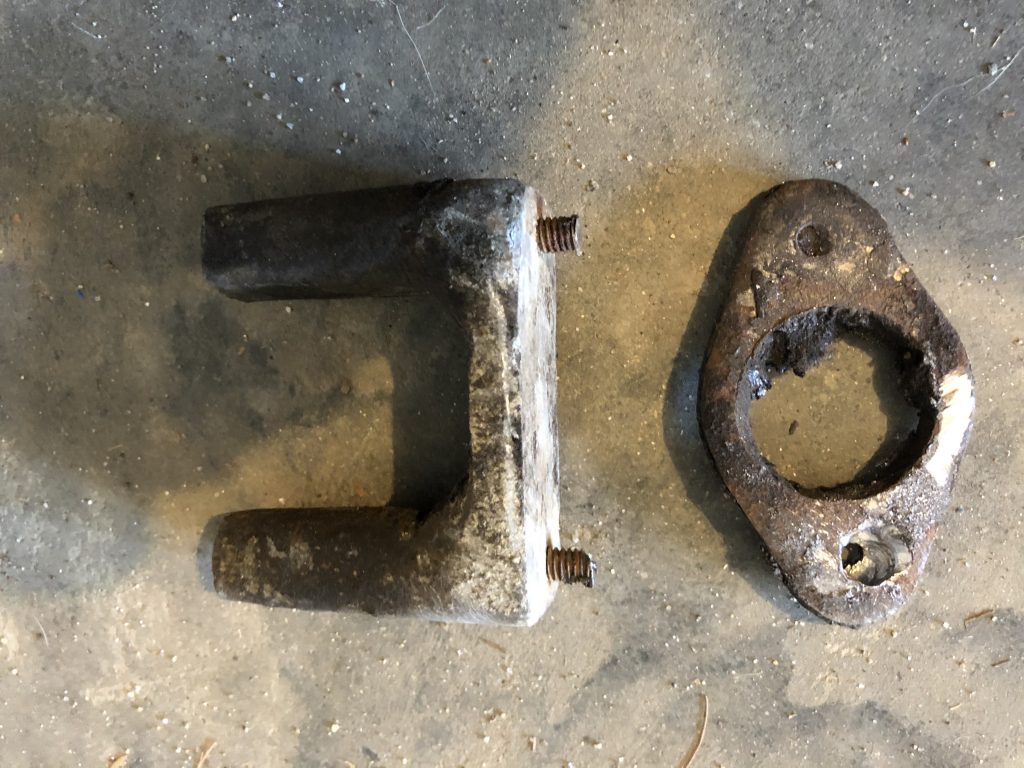
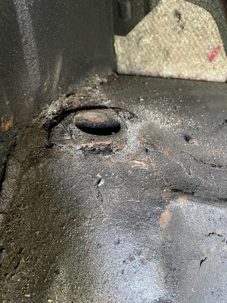
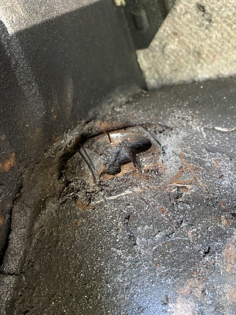
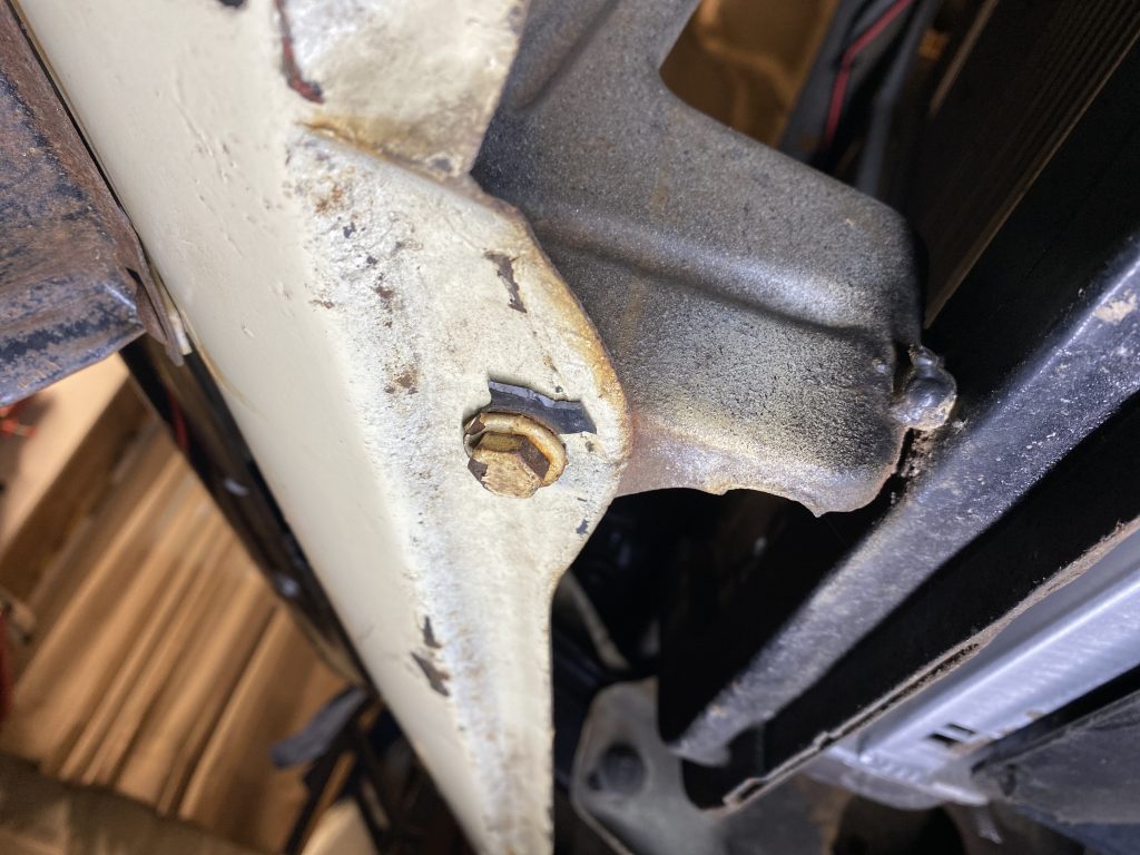
I gave it a good pull with a breaker bar, but the bolts were not moving. I sprayed it down with some penetrating oil, and gave the bolts a try and more oil every day for about a week. I felt them start to budge and cranked harder…only to have the bolt snap and the head twist off. It turned out that the extender was aluminum, the bolts were steel, and they had corroded together so there was no way they’d ever come apart.
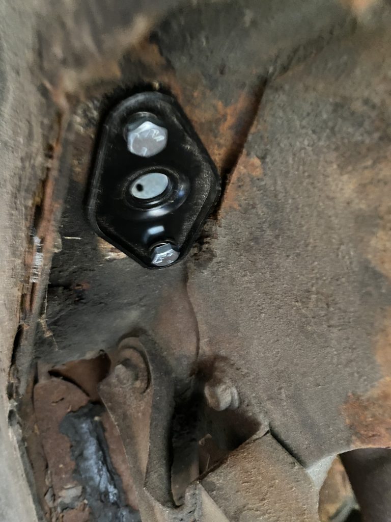
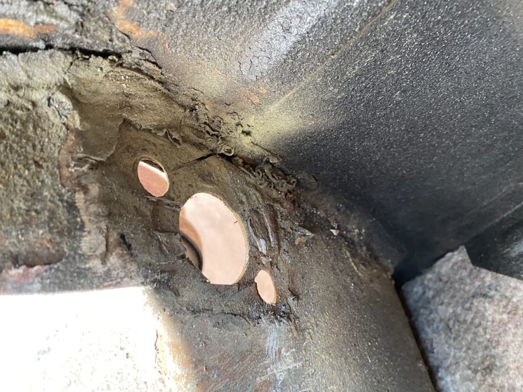
The rear upper shock mounts are two pieces. A thick plate inside the trunk with threaded holes, and another thinner plate under the car that is attached with bolts into the threaded holes in the thick plate, sandwiching the trunk floor in between. I ended up drilling the bolts out of the thick plate and cutting it away until it let loose. Not a fun job.
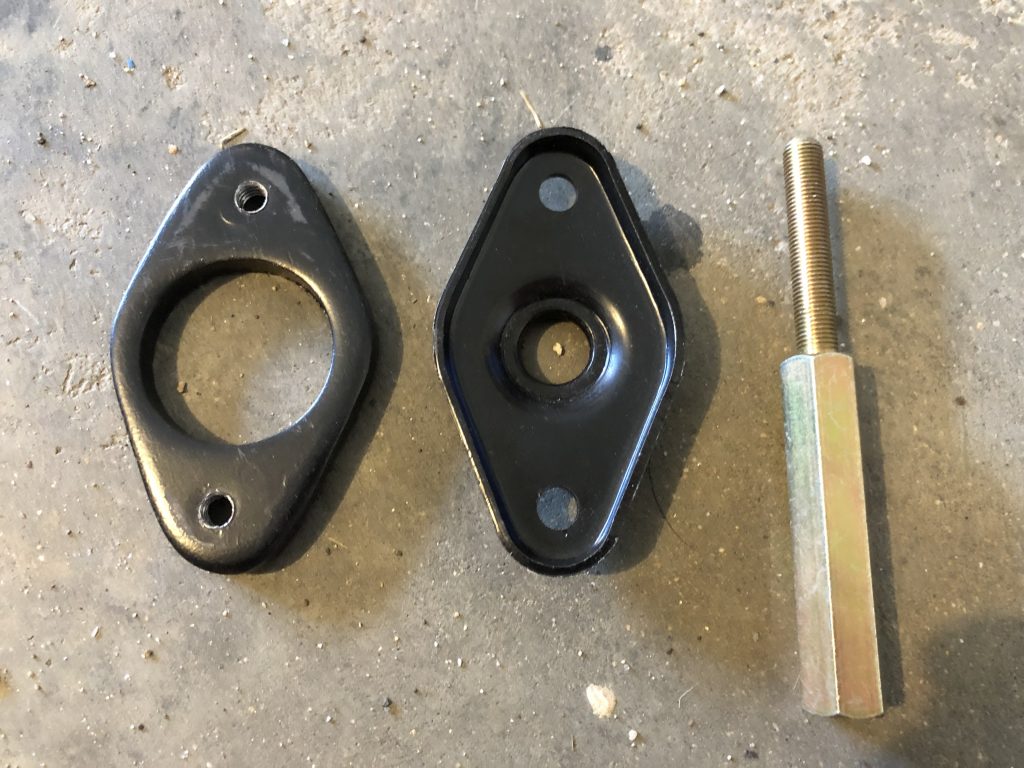
I could not find a similar design shock extender, so I ended up with a version that screws onto the top stud on the shock that makes the stud longer. Different design, but same effect. I put it back together with replacement upper shock mount brackets, and the stud extender on the original shock.
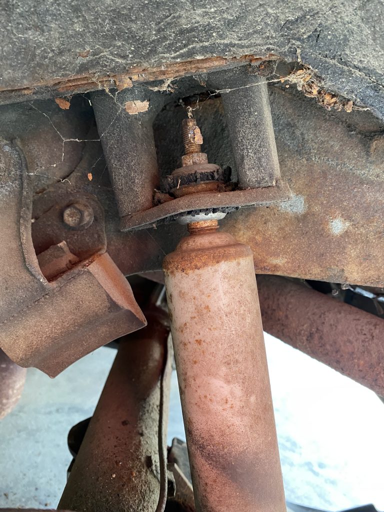
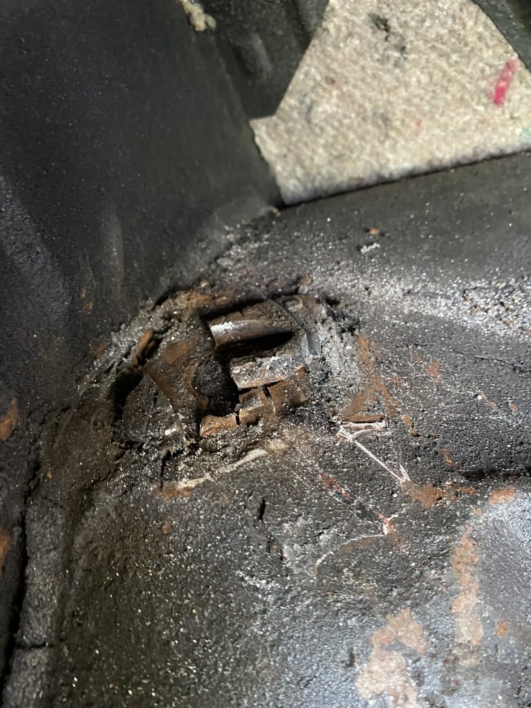
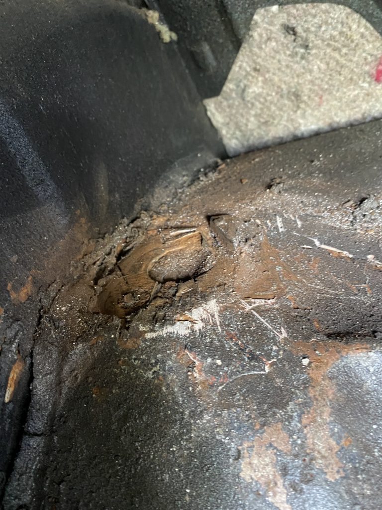
Back to today’s shock replacement: Remembering how difficult it had been to remove the right one, I was not looking forward to doing that same job on the left rear upper shock mount, but it had to be done. It took me 3 hours to get the mount bracket off, but I did succeed.
Removing the bracket…
Assembly:
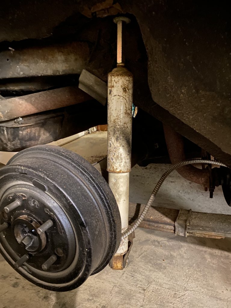
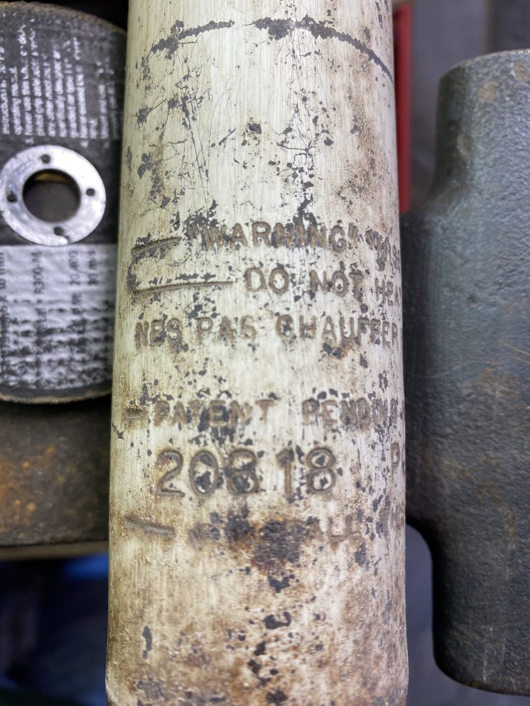
The old shock turned out to be a no-name model marked “20818” and “POF22MC1R”, neither of which seem to turn up as the correct shock for a 1st gen F-body. It was a little shorter than the new shock, but not by much, maybe 1/2″. I had checked the travel in the new shocks, and it was about 7″
Once the new upper shock mount bracket was bolted into place, I started to test fit my new Bilstein shock, and discovered that the lower mount had been bent to fit the narrower lower eye mount of the old shock. I was able to bend the bracket back into shape. It was around this time that I discovered that my stud extender piece had a fine thread (as did the old shocks) but the new shocks were coarse thread, and probably also metric. That meant the extenders weren’t going to work on the new shocks. I decided to check the length anyway. With the car supported under the shock mount, it was at the normal ride height. I had to compress the shock about 3″ to get it seated, which worked out to about half the overall travel, which seemed correct.
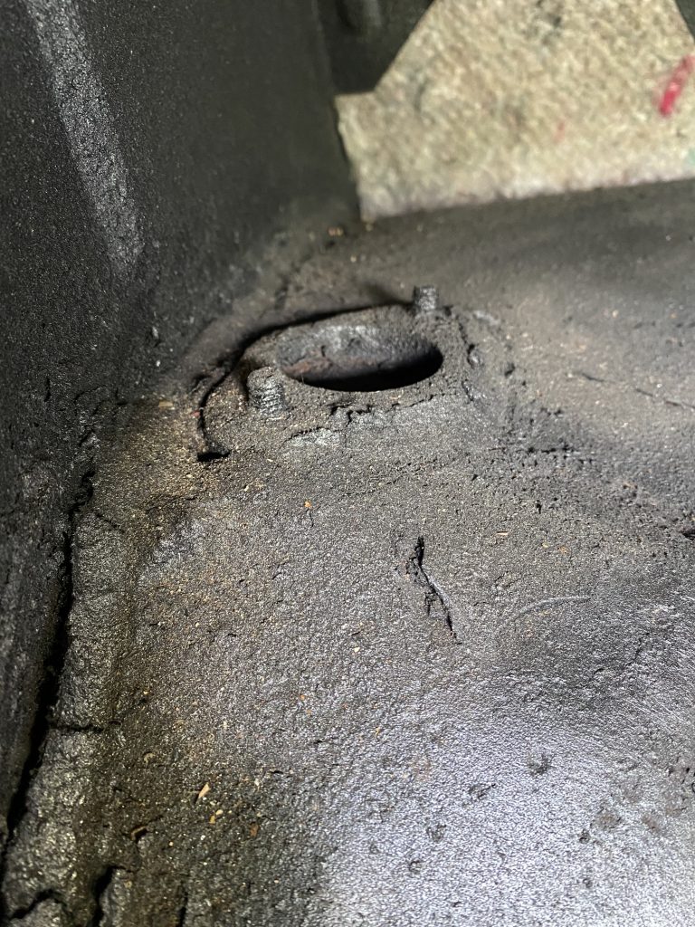
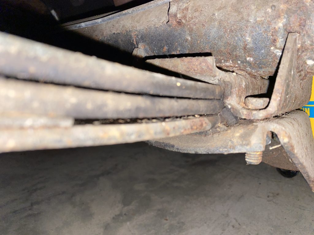
Then I looked closer at the spring pockets on the diff, and realized they were for monoleaf springs, which means a) the springs aren’t properly installed, but also b) I didn’t need the longer shocks with my monoleaf bracket setup.
Given that the old and new shocks (fully extended on the workbench) were about the same length, and the new shocks had about 7″ travel, I think the 3″ shock extenders were putting the old shocks near the bottom of their travel limit. When the car hit a big bump, the shock would compress until it bottomed out…which was likely a major cause of the rough ride.
The right side was much easier since I had already replaced the upper mount.
After I got it put back together, I took it for a test drive on some bumpy roads. The roads were still bumpy, but at least the car doesn’t sound like it’s coming apart when I hit those bumps. Much improved!!!
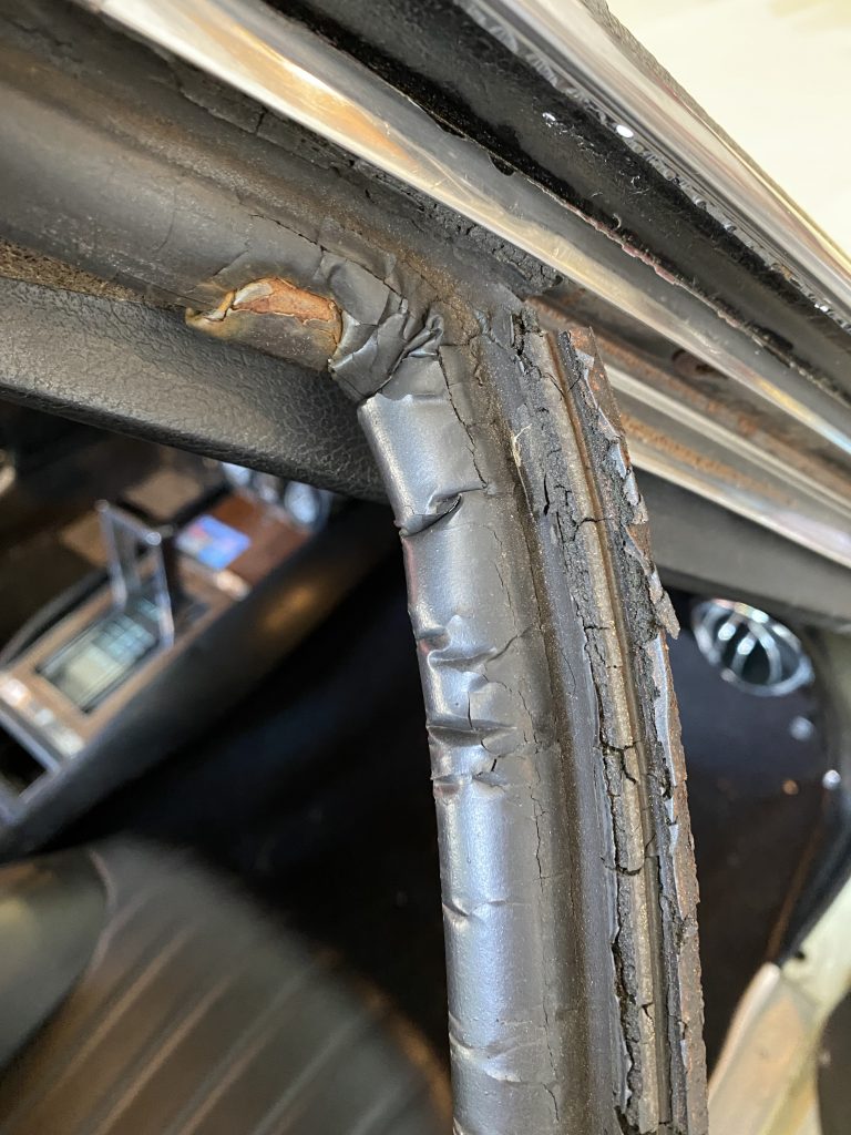
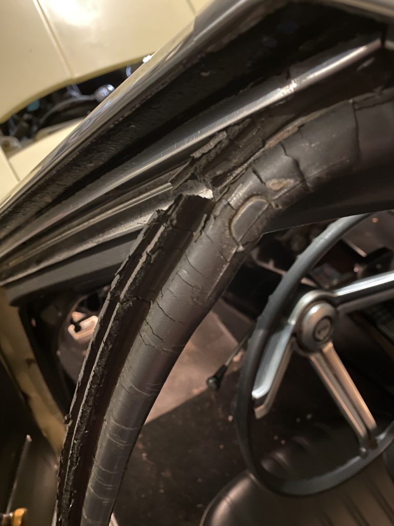
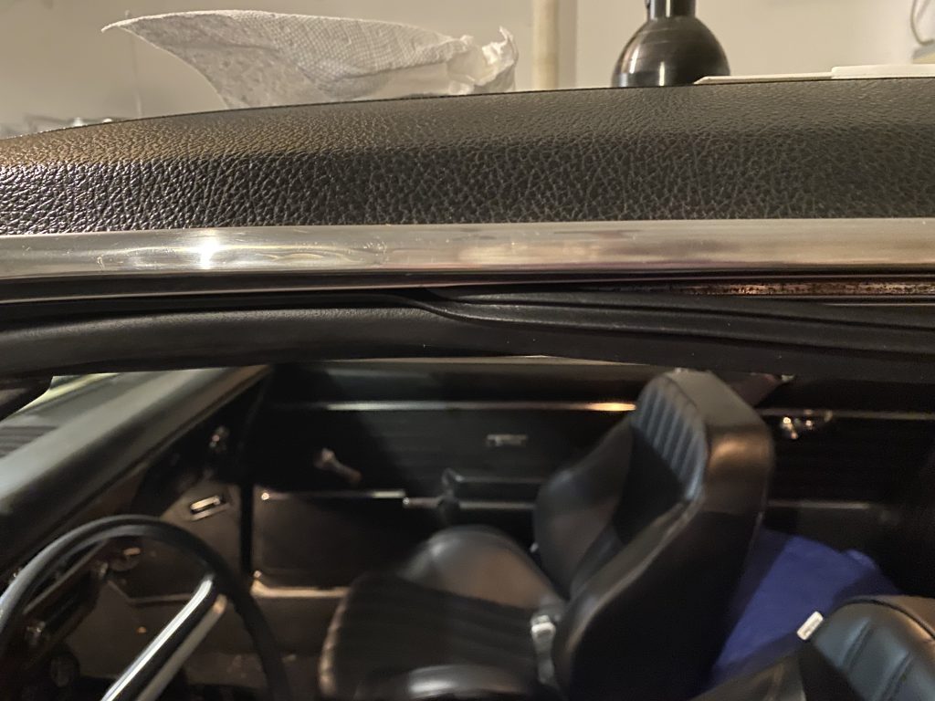
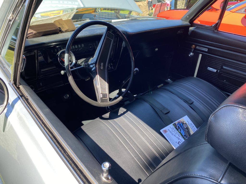
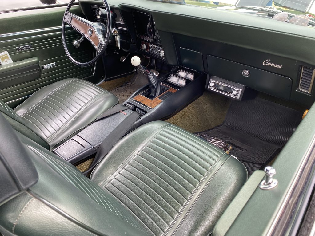
The roof rail weatherstripping on the car is probably the original stuff, and after 55 years, it doesn’t really do its job very well. I bought a bunch of weatherstripping for the car when I first bought it, and have slowly been installing it on the car ever since. I decided it was time to do the roof rails.
The installation turned out to be very simple. The old weatherstripping just pulled out of the roof rail channel. The instructions say to add a little weatherstrip adhesive at the corner near the top of the windshield, and a little at the frontmost part with the little plastic buttons, but you don’t have to put it anywhere else.
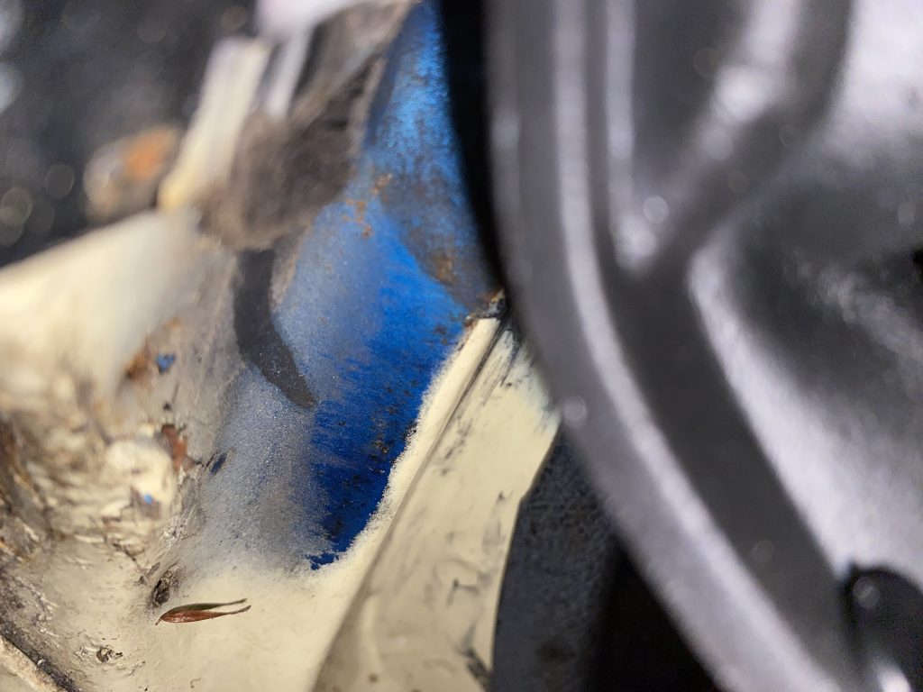
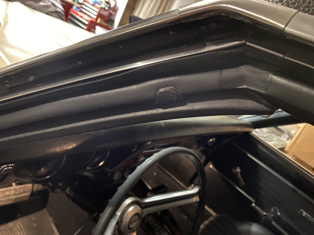
Some of the original blue color of the car showing from under the weatherstrip:
The installation turned out to be very simple. The old weatherstripping just pulled out of the roof rail channel. The instructions say to add a little weatherstrip adhesive at the corner near the top of the windshield, and a little at the frontmost part with the little plastic buttons, but you don’t have to put it anywhere else.
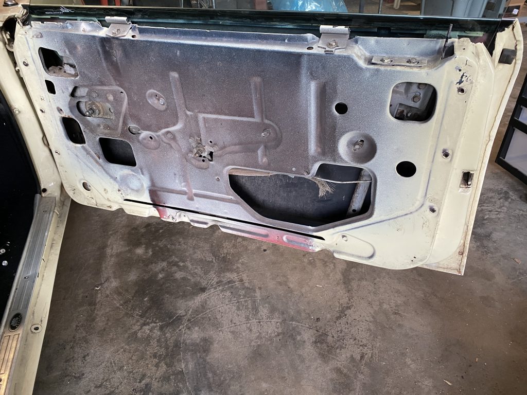
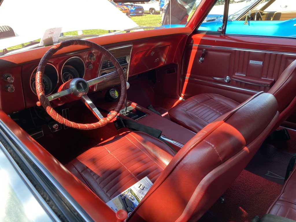
The other job was replacing the outer door window ledge weatherstrip, and then fixing the window alignment so it hit the roof rail weatherstrip in the proper spot. The videos in the post about fixing the window so it rolled all the way down helped a lot here.
Getting to the window adjustments means taking off the door upholstery panel.
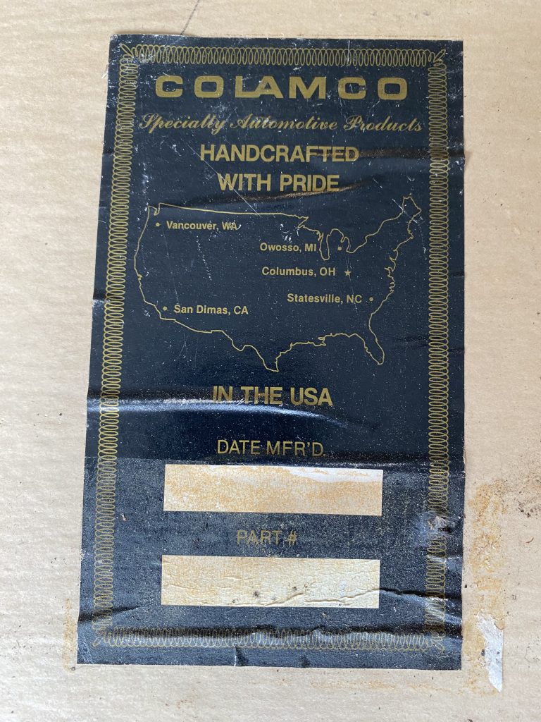
The panels are reproduction pieces from a company called COLAMCO that has since gone out of business. Too bad, they appear to be very well made. I wish I could read the manufacturing date, but it’s too faded.
I’m not 100% happy with the window alignment, but it’s pretty close. I still have some work to do on the rear window, and I will need to adjust both so they mesh properly.
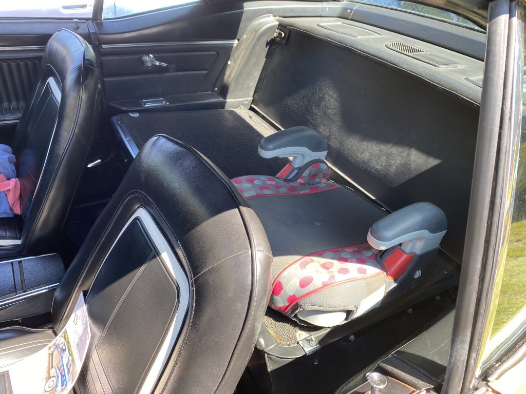
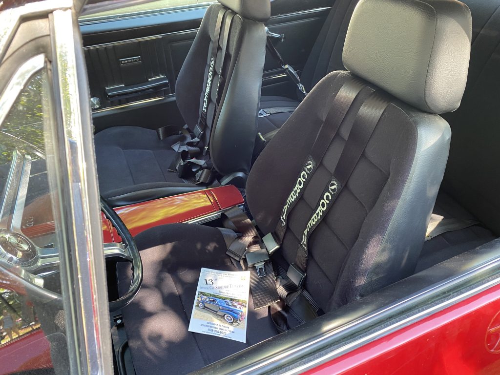
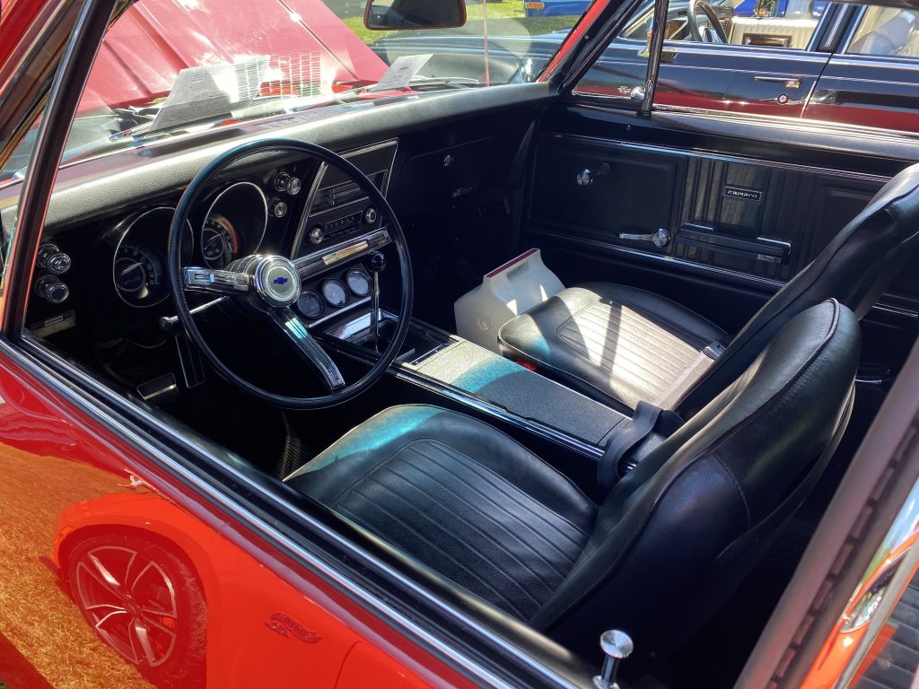
When I first installed the Scat/ProCar Rally seats, the seating position seemed at least 2-3″ taller than the stock seats. Granted, the stockers were pretty worn out, but the seating position still bugged me.
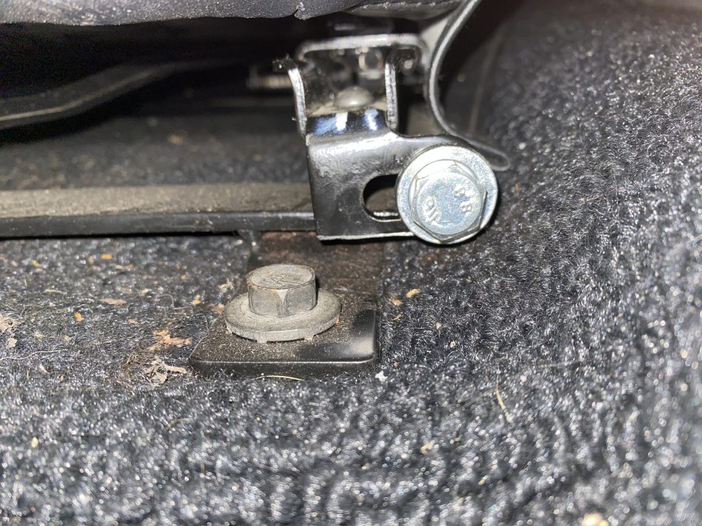
I finally got around to lowering the seats on the brackets.
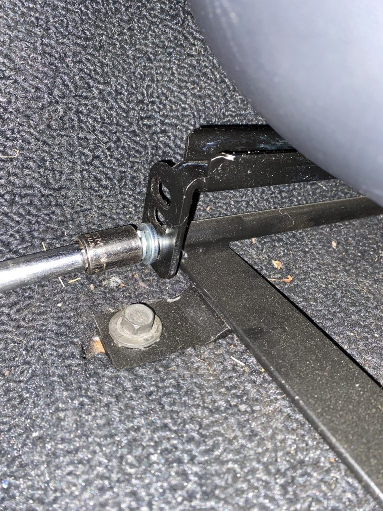
There’s 3 positions available on the seat brackets. Unfortunately, there’s not enough clearance between the floor bracket and the floor to use anything other than the bottom (tallest) position on the seat bracket. In order to use the shorter positions, the seat bracket has to be cut.
/
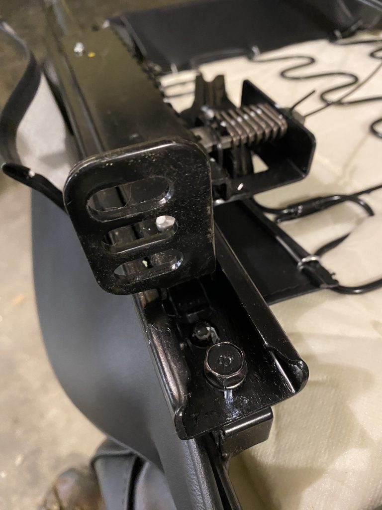
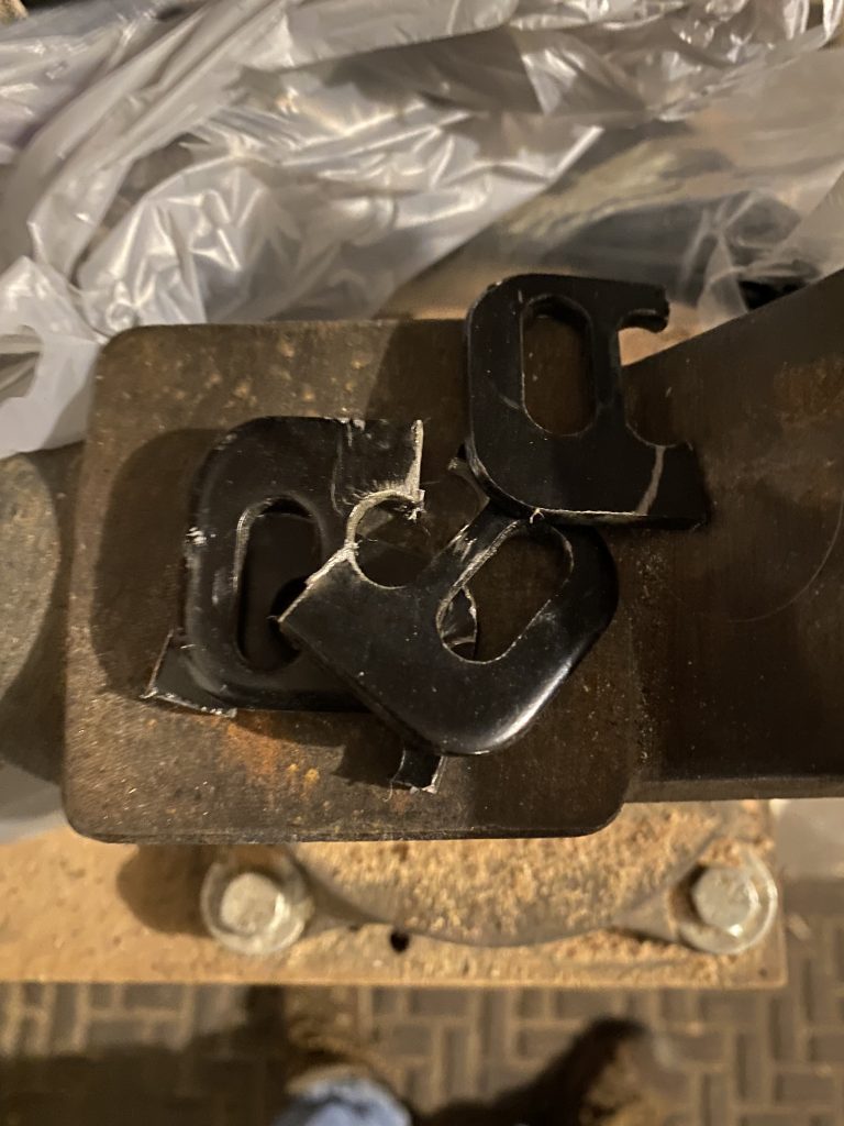
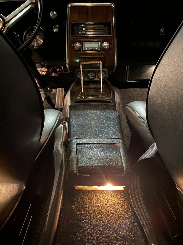
I went all the way and cut the bottom two positions off of the seat mounting brackets. This puts the seat as low as it can possibly be. Reinstalling the rear bracket bolts was a big fight, as the slider mechanism hits the floor bracket when it’s installed in the shortest slot of the seat bracket.
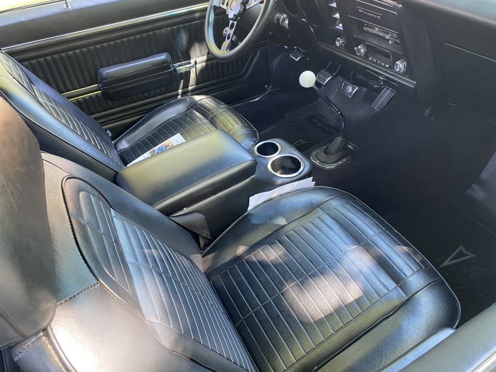
The result is that the seat is about 1″ lower than it was originally, which is an improvement. I’d personally like to see it drop by another inch, but I don’t see any way to make that happen. I haven’t driven it yet with this modification, so it may be fine already.
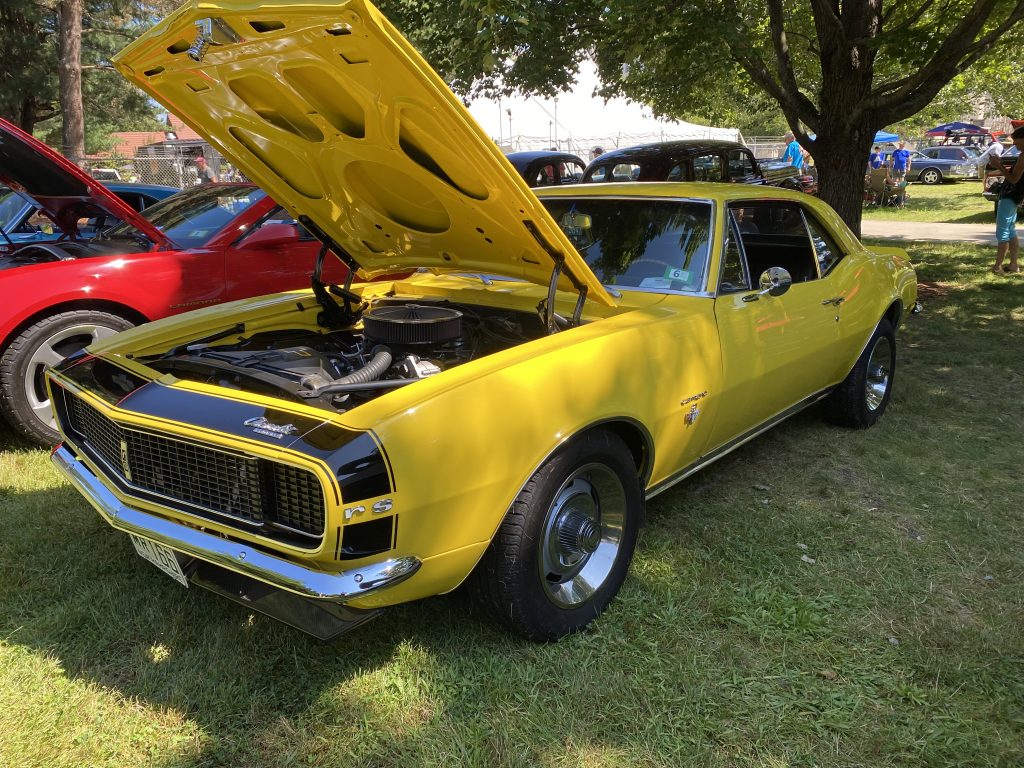
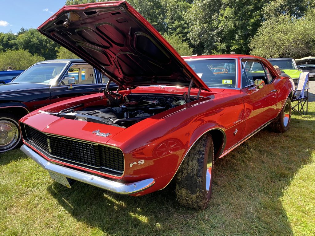
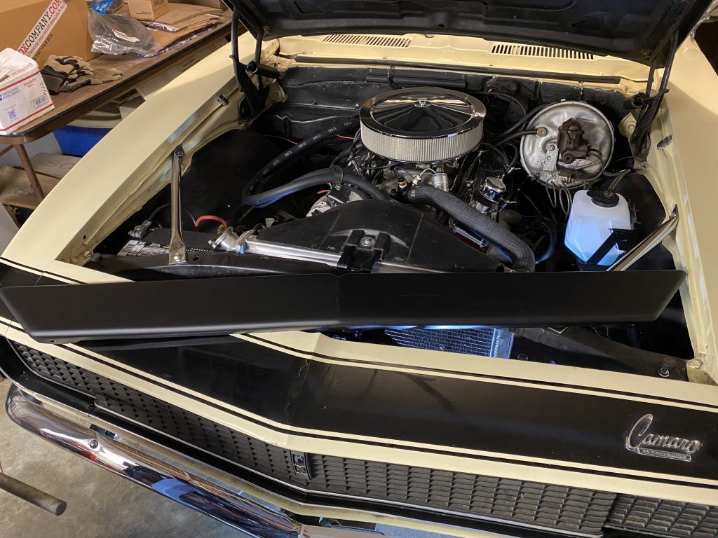
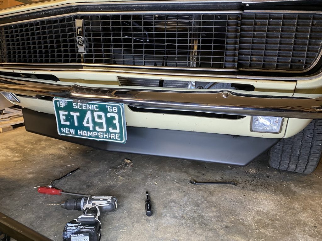
I uncovered a chin spoiler in my parts pile that I had purchased early on, but had gotten buried in other things in the garage. The spoiler is from OER, and is plastic. I also purchased struts and a fastener kit for it.
The top edge of the spoiler attaches to the lower edge of the front valence panel with several bolts. The center attachment point uses the lower hood latch support bracket bolt. That part went very smoothly. The problems started with the struts.
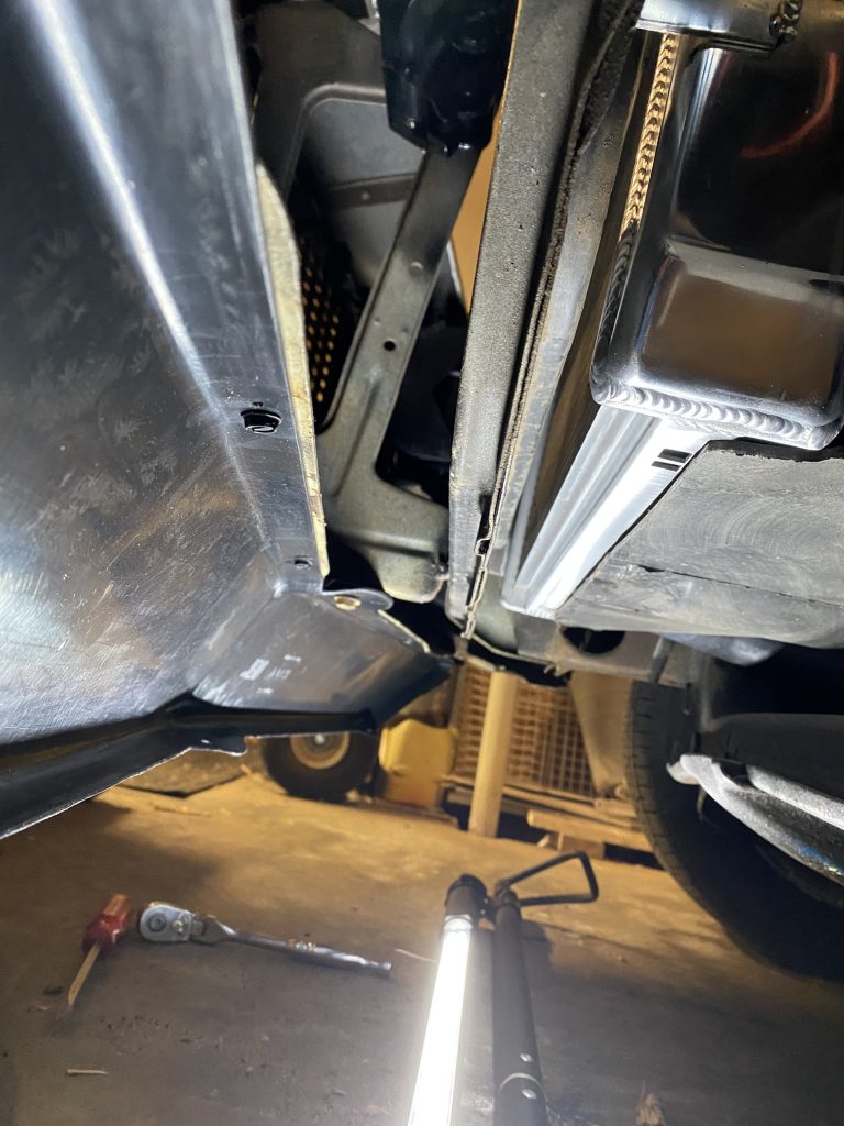
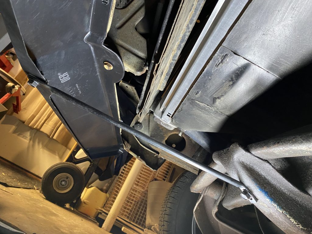
There are 3 struts in the kit. When I was working out the installation, I did some reading and found out there is conflicting information about the struts. The center strut was pretty straightforward. That goes from the front center of the spoiler to the front of the skid plate in the middle of the subframe. The two side struts are where the questions come in. Some things I found said that they should go to the lower front fender edge. Others said they don’t really go there, and if you hit a curb with the spoiler, that will bend and damage the fenders. Another theory was that the struts work with the stock GM spoiler, but don’t work with the reproduction ones. Yet another writeup described running them straight back and attaching them to the bumper brackets.
In the end, I decided to only install the center strut. I drilled a hole in the skid plate for the bolt, and left the outside struts off. It’s solidly mounted, and seems ‘good enough’ for now.
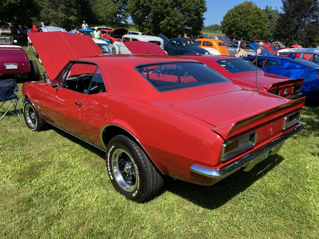
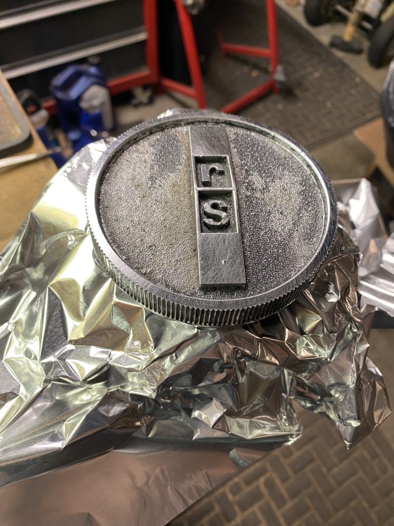
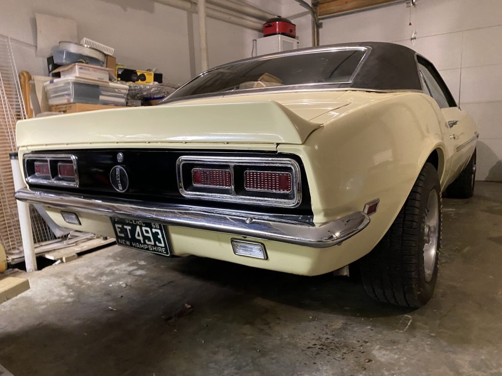
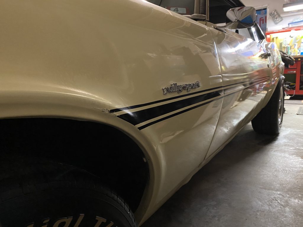
After weeks of sanding, buffing, and polishing, the car was finally starting to look a little shiny. While I know the black accent color on the rear panel is supposed to be slightly matte finish, I decided to hit it with the polisher anyway. The results were really good, except that the gas cap looked really shabby by comparison. As with the other RS-specific parts on the car, I’m pretty sure the gas cap is an original GM part, so I decided to spruce it up a bit.
The first step was removing all the old paint. I used a few rounds of brakleen to get rid of most of it.
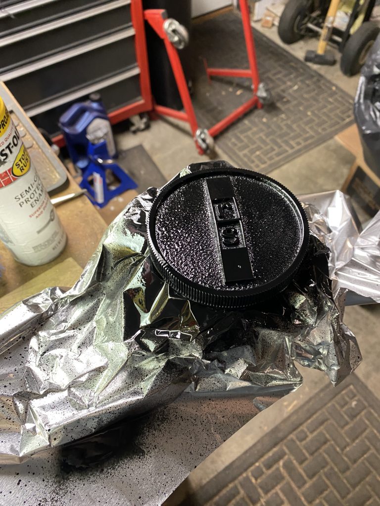
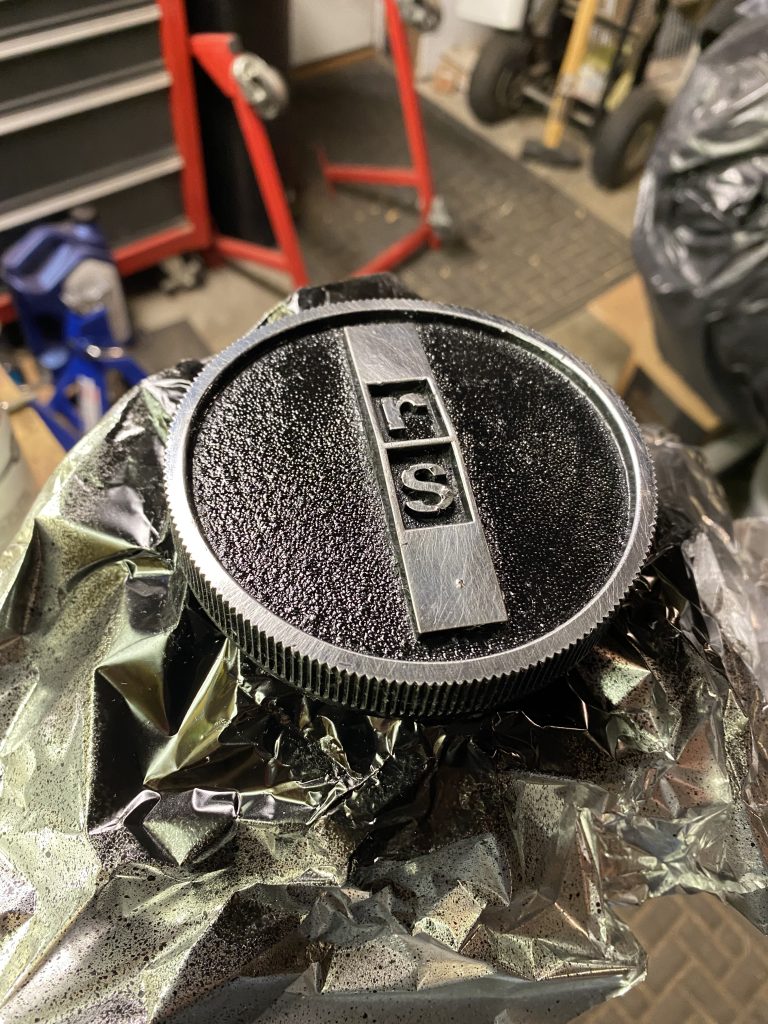
The rest of the operation was pretty much the same as what I did for the rally rim center caps. Spray everything black, wait for it to dry a little, then wipe the raised areas clean with a paper towel sprayed with brakleen.
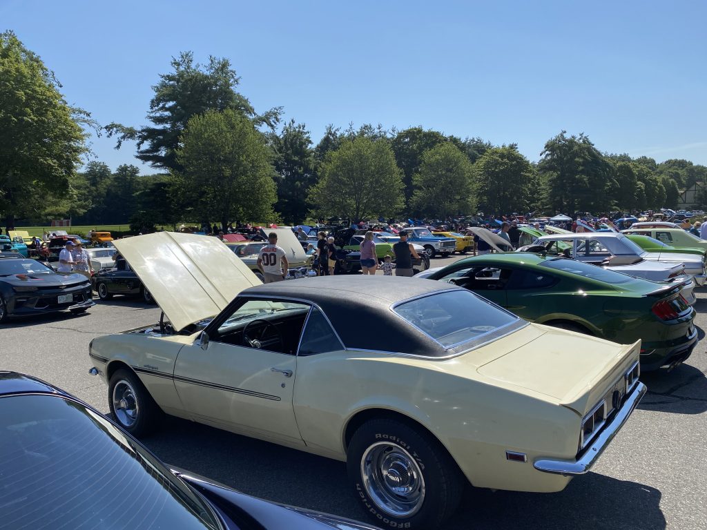
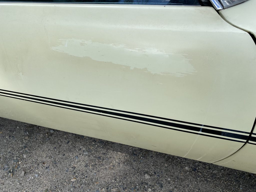
The paint on the car has good points and bad points. The D90 stripe stencil and black paint was applied fairly well. The yellow base coat has a giant run in it front and center on the hood. The clear coat is very uneven, puddled in some places, and was barely fogged on in other places. Overall the car had a matte look to it, as the clear dulled everything.
Figuring I had nothing to lose, I started experimenting with ideas to get some shine back. I first started with just paste wax, that turned out to be far too gentle. Next I tried polishing compound, which was also not aggressive enough. Same for rubbing compound. The problem was the clearcoat was very thick in some areas, and had not adhered in others, leaving a blotchy, dull look. The only answer was to take as much of the clear off as possible.
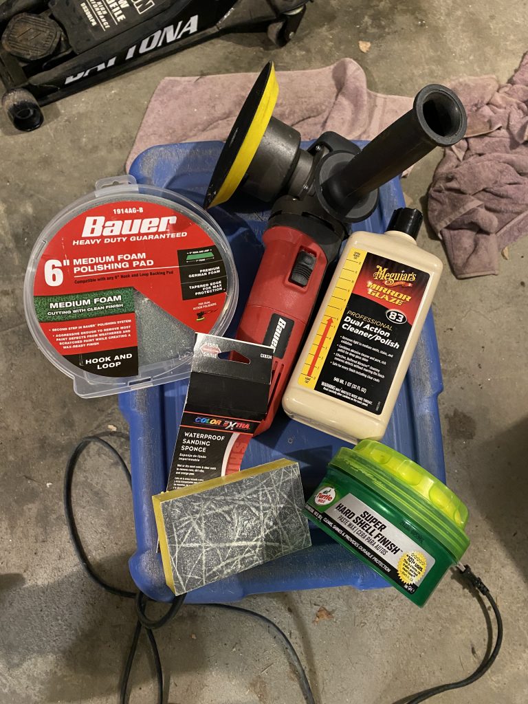
I ended up having the best success wet sanding with a 1500 grit sponge sanding block, followed by polishing compound applied with an electric buffer on a medium pad, and finishing with paste wax on a fine pad. Not perfect, but a lot better than it had been.
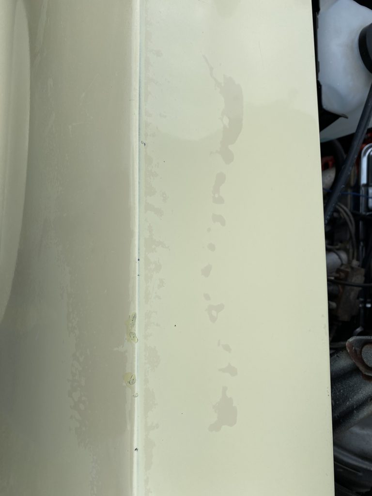
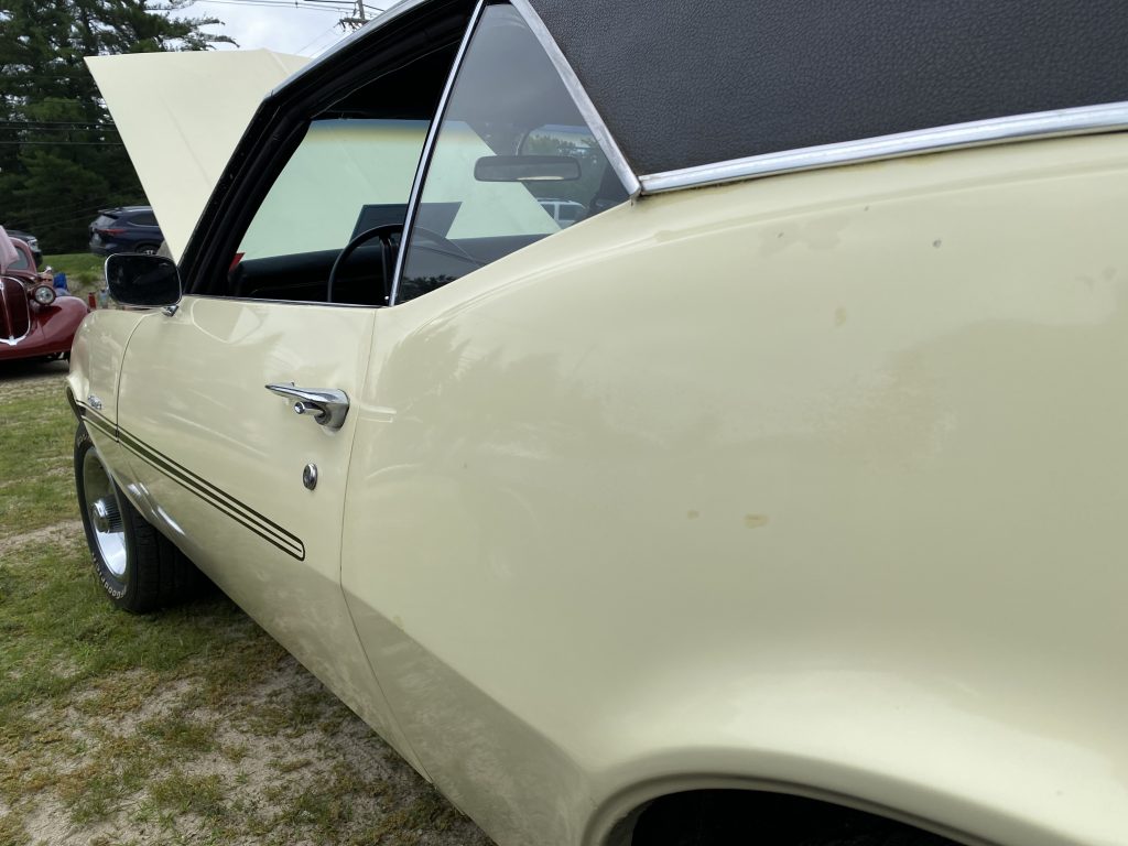
Even after working on it over a period of several months, there are bad spots, such as this pool/drip on the top of the LH front fender. The dark splotches are what’s left of a puddle of clear that was there. I’ve also pushed this as far as I feel safe, you can see where the yellow has started to wear through to show the darker paint underneath at the outer edge.
The final (for now) results are far from perfect, but they are a lot better than I was expecting they would be
There’s still more work to do, and I’ll keep picking away at it, but I like the results so far.
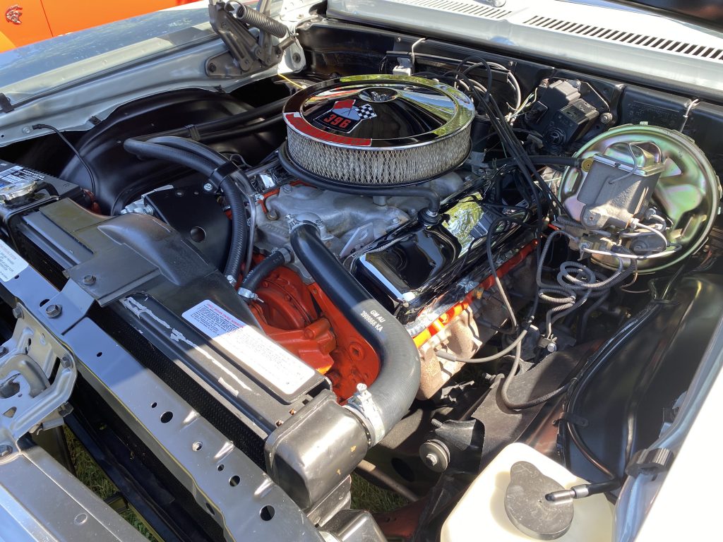
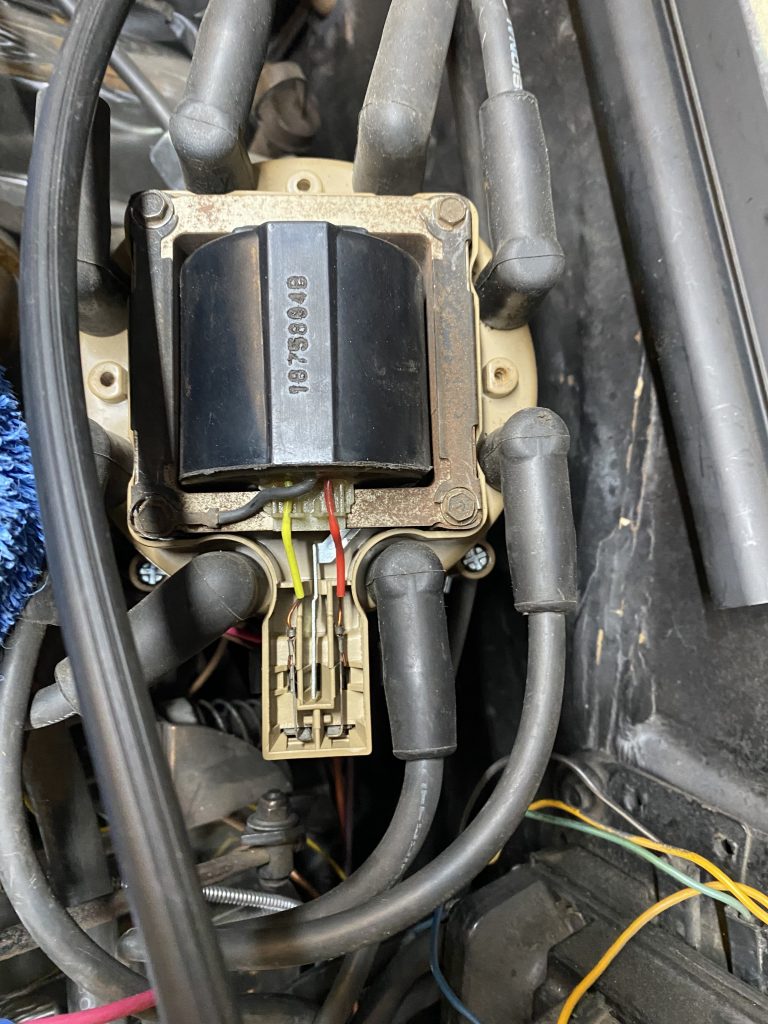
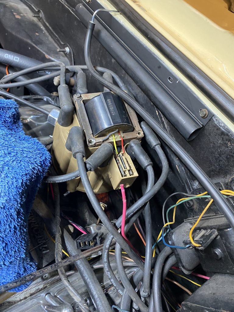
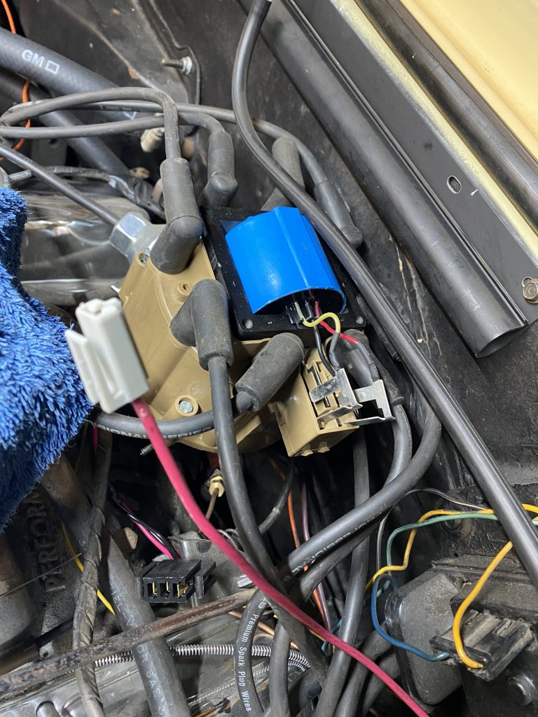
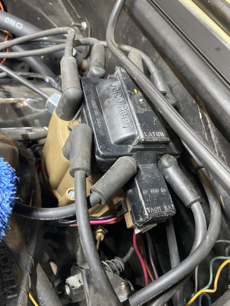
When I replaced the distributor, the new one did not come with a new coil. I reused the old one. Although it’s been working fine, I wasn’t happy that it still was using the old coil. I bought a replacement and installed it. Not too tough of a job, but it’s good to have new parts in there.
I also replaced the generic terminal on the end of the distributor power wire with the correct terminal and shroud. Now it plugs in just as intended.